190-01115-01 G3X™/G3X Touch™ Avionics Installation Manual
Rev. AV Page B-16
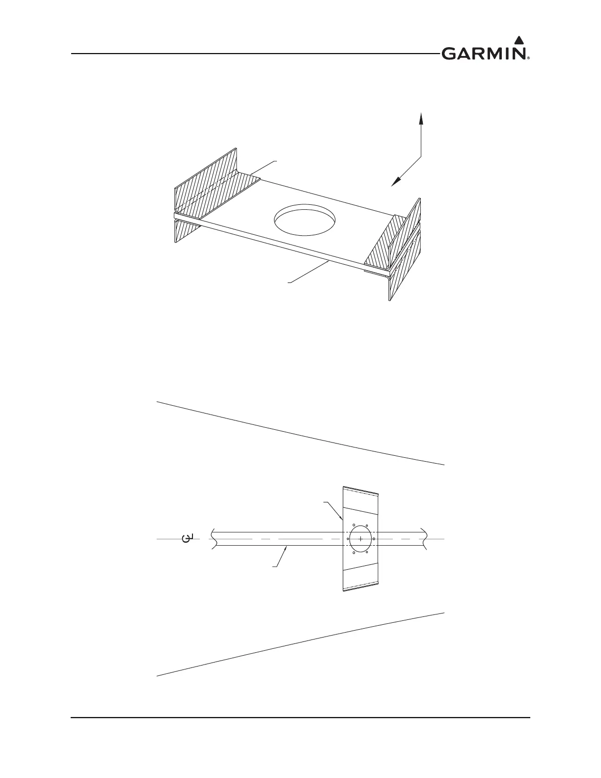
5. Secure the shelf to the fuselage with one layer of 3.0 in. wide, 2 bid strips at each corner above and
below the shelf. The lay up is shown in Figure B-23.
Figure B-23 Magnetometer Shelf With Lay up
6. The shelf installation must be fully cured before proceeding with the magnetometer installation.
Using the elevator control tube as the aircraft centerline reference, project a parallel line on to the
magnetometer shelf. The parallel line serves as an indication of the aircraft’s forward direction, as
shown in Figure B-24. The alignment of the magnetometer is critical and needs to be within 0.5°
of the aircraft’s forward direction.
Figure B-24 Alignment Of Magnetometer Cutout With Aircraft’s Forward Direction
MAGNETOMETER SHELF
3" WIDE, 2 BID STRIPS, 4 PLACES
UP
FWD
ELEVATOR CONTROL TUBE
MAGNETOMETER SHELF
 Loading...


