Chapter 3 Page no. 302
Cables.FM
GE Healthcare Senographe DS
Revision 1 Service Information and Procedures Class A 2385072-16-8EN
Cable Lay-out and Pin-out
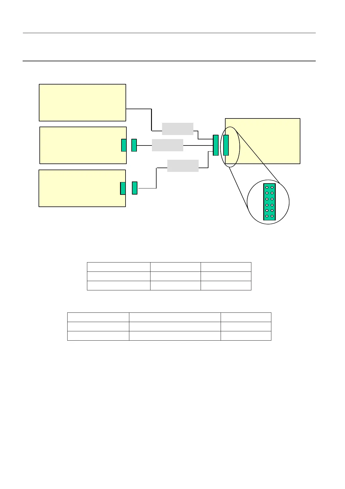
1-17. W114/W116/W209 - PDU Board J7 Connections
W114 - Column Fuse Check
PDU Board PL101 J7 Pin 1 to Terminal 2 ST102-F1/1.
W116 - PL104 power
PDU Board PL101 J7 to Interface Board PL104 J1.
W209 - 48 V LP
1
PDU board PL101 J7 to Lift Board PL201 J2:
1-18. W116 - PL104 Power
See W114/W116/W209 - PDU Board J7 Connections on page 302.
1-19. W117 - Terminal Block Interconnection
Terminal block ST102 from F1/2 to F2/2.
1-20. W119 - Serial Link TX Generator to Interface Board
Generator Interface J7 to Interface Board PL104 J9.
Pin no. Level Pin no.
PL 104 J1-1 +48 V PL 101 J7-5
PL 104 J1-2 GND PL 101 J7-11
Pin no. Functions Pin no.
PL 201 J2-1 + 48 Volts (max. 100 mA) PL 101 J7-3
PL 201 J2-2 GND PL 101 J7-9
J1
W114
PDU
Board
PL101
J7
W116
W209
Interface
Board
PL104
J2
Lift
Board
PL201
Fuse2 on
TerminalBlock
ST102
7
8
9
10
11
12
1
2
3
4
5
6
 Loading...


