GE HEALTHCARERAFT VOLUSON E8 / VOLUSON E6
D
IRECTION KTD102576, REVISION 7 DRAFT (AUGUST 23, 2012) SERVICE MANUAL
5-36 Section 5-4 - BackEnd Processor
5-4-6 RTB - Distribution Board Bottom
Function of the Distribution Board Bottom (RTB):
• USB2.0 Interface, Board is connected to PC via USB cable
• 5 port USB2.0 Hub for connecting Peripherals
• Feed through DC-Power and Signals for the Console (12V_ATX, 5V_ATX, 5VSB, PWR_On,
Start_Key, Loud speaker)
• Connector for ECG –Preamplifier (optional)
• Multiplexer and Amplifier for PC-Sound, Doppler Audio and VCR/DVD-Recorder
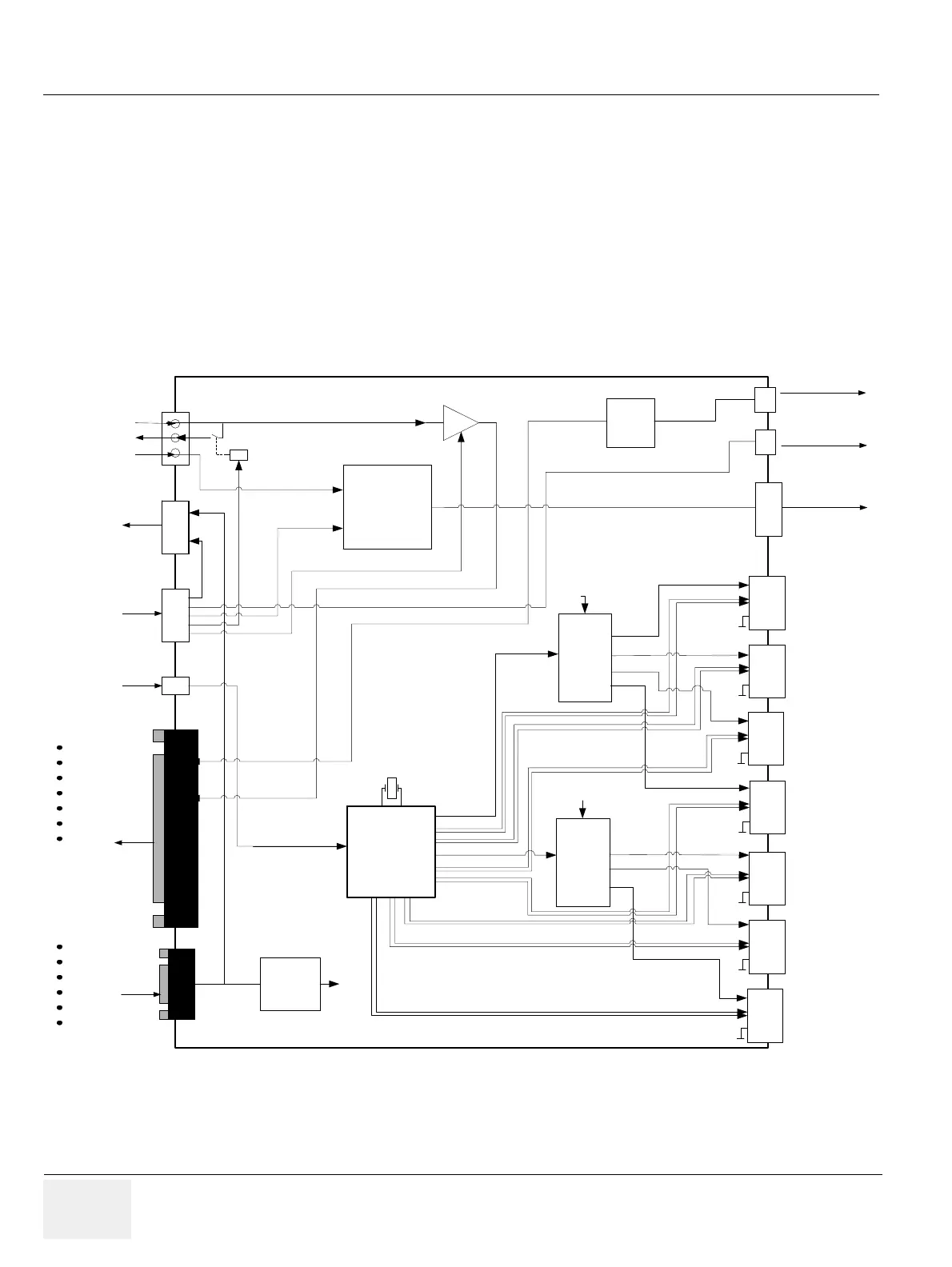
5-4-6-1 RTB - Block Diagram
Figure 5-13 RTB - Block diagram
3V3
Voltage
Regulator
USB 2.0 Hub
Controller
7 Port
USB
Port
Power
Switch
USB
Port
Power
Switch
USB-
Out
USB-
Out
USB-
Out
USB-
Out
+5V
+5V
+5V
+5V
DP1
DM1
DM2
DP2
DM4
+5V
+5V
DP4
DM5
DP5
DM4
DP4
1
2
5
3
4
3V3
MUX
Speaker
PWR_on
Start_Key
+5VSB
+5V_ATX
+12V_ATX
GND
+5VSB
+5V ATX
+12V_ATX
GND
PWR_On
Start_Key
USB in
RFI
ECG
PC Out
VCR Rec.
VCR Pb.
VCR Pb.
Doppler
Audio
Audio Signal
RTB
+5V, +12V
ECG
VGA Interrupt
To PC
Aux/CD in
Volume
Control
USB-
Out
USB-
Out
USB-
Out
+5V
DM3
DP3
+5V
67
DM6
DM7
+5V
DP6
DP7
VCR Rec. Select
USB Power Ctrl
USB Power Ctrl
Power ON
Power
ON
Logic