GV-AS410 / 4110 / 810 / 8110 Controller
109
5
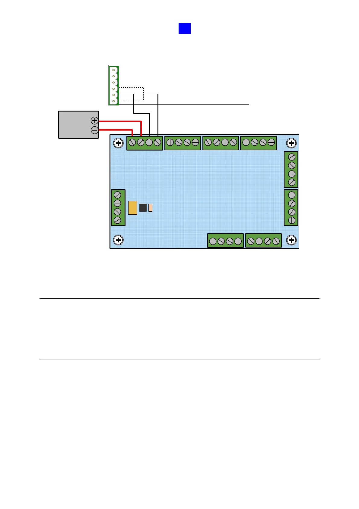
2. Connect the ED + / - pins to the (+) and (-) points on the output device (ex: electric lock).
+
+
-
-
ED -
ED+
COM
NC / NO
ED -
ED+
COM
NC / NO
NC / NO
COM
ED+
ED -
NC / NO
COM
ED+
ED -
NC / NO
COM
ED+
ED -
NC / NO
COM
ED +
ED -
ED -
ED+
COM
NC / NO
NO
COM
NC
Output
Device
GV-AS410 / 4110 / 810 / 8110
Power Adapter Board
ED -
ED+
COM
NC / NO
Figure 5-14
3. When all connections are completed, connect the power supply to a 110-120V power
source.
Note:
1. The power supply of GV-AS410 / 4110 / 810 / 8110 Kit comes in US standard and EU
standard. Make sure the device is connected with a voltage within its voltage range.
2. You can place a backup battery in the supplied battery casing, and connect the backup
battery to the GV-AS410 / 4110 / 810 / 8110 board. Refer to 5.2.4 Connecting Backup
Battery for details.

 Loading...


