46
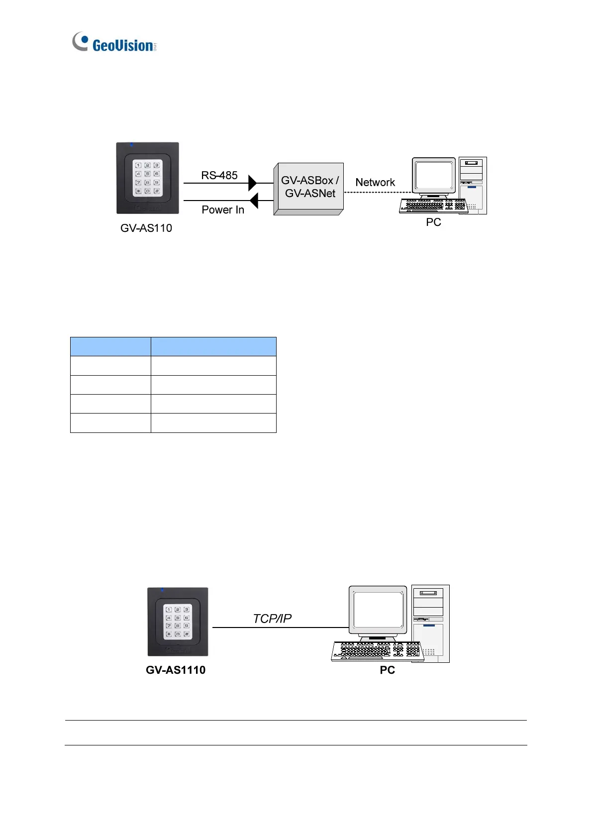
Network Connection between GV-AS110 and PC
The figure below illustrates the network connection between GV-AS110 and the computer.
For this connection, a GV-ASBox or GV-ASNet is required.
Figure 2-10
Connect two power wires and two RS-485 wires from GV-AS110 to GV-ASBox / GV-ASNet.
The table below shows the wire assignments of RS-485 connection on GV-AS110.
See 9.1.4.A Connecting GV-AS100 / 110 / 120 or 9.2.4.A Connecting GV-AS100 / 110 / 120
to see how to connect to GV-ASBox or GV-ASNet.
2.2.4.B Connecting GV-AS1110 to PC
The figure below illustrates the network connection between GV-AS1110 and the computer.
Figure 2-11
Note: GV-AS1110 is only compatible with GV-ASManager V4.2.3 or later.
Wire color Definition
Red 12V
Black GND
Blue RS485 +
Light Blue RS485 -

 Loading...


