68
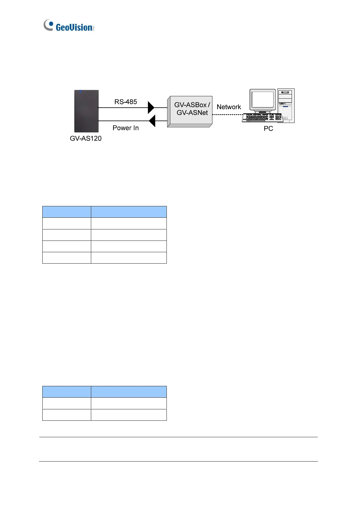
3.2.4.B Network Connection
The figure below illustrates the network connection to the computer. For this connection, a
GV-ASBox or GV-ASNet is required.
Figure 3-8
Connect two power wires and two RS-485 wires from GV-AS120 to GV-ASBox / GV-ASNet.
The table below shows the wire assignments of RS-485 connection on GV-AS120.
See 9.1.4.A Connecting GV-AS100 / 110 / 120 or 9.2.4A Connecting GV-AS100 / 110 / 120
to see how to connect to GV-ASBox or GV-ASNet.
3.2.5 Connecting the Power
The supplied AC adaptor can be connected to any power source supplying from 100 to 240V.
Connect 12V and GND wires to the supplied power adapter and then connect the power
adapter to a power source. The table below shows the pin assignments of the power
connectors on GV-AS120.
Note: Power should only be applied to the unit when all connections are completed and
tested.
Wire color Definition
Red 12V
Black GND
Blue RS485 A+
Light Blue RS485 A-
Wire color Definition
Red 12V
Black GND

 Loading...


