GV-AS110 / 1110 Controller
45
2
2.2.4 Connecting to the PC
Connecting GV-AS110 / 1110 to a computer allows you to access its Web interface and
connect it to GV-ASManager if the computer is installed with GV-ASManager. The computer
running GV-ASManager software can be used to monitor the access information and alarm
messages from the controller. The communication link between the computer and GV-
AS110 / 1110 is as below:
GV-AS110: RS-485 connection or network connection
RS-485 connection: a RS-485 to RS-232 converter is required
Network connection: an optional GV-ASBox or GV-ASNet is required
GV-AS1110: Network connection
2.2.4.A Connecting GV-AS110 to PC
RS-485 Connection between GV-AS110 and PC
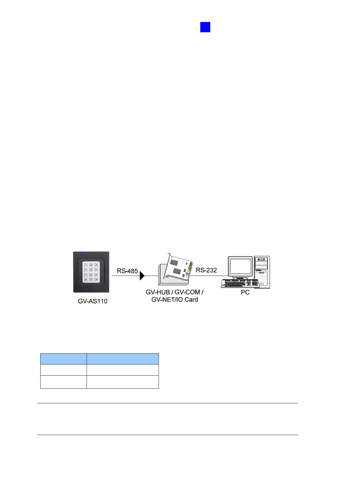
The figure below illustrates the RS-485 connection between GV-AS110 and the computer.
For this connection, a RS-485 to RS-232 converter between GV-AS110 and the computer is
required. You can use GV accessories, such as GV-Hub, GV-COM and GV-NET/IO Card,
as the RS-485/RS-232 converter.
Figure 2-9
The table shows the wire assignments of RS-485 connection on GV-AS110.
Note: When connecting multiple GV-AS110 through RS-485 connection, you can use the
keypad on GV-AS110 to program every unit’s ID. See 2.3.2 Programming the GV-AS110 /
1110.
Wire color Definition
Blue RS485+
Light Blue RS485-

 Loading...


