EasyManuals Logo

GeoVision GV-AS1010 User Manual

GeoVision GV-AS1010
235 pages
To Next Page IconTo Next Page
To Previous Page IconTo Previous Page
Page #194 background imageLoading...
Page #194 background image
176
9.1.4.D Connecting Input Devices
GV-ASBox provides 8 inputs (DI1 to DI8). All inputs are dry contact and can be configured
as normally open (NO) or normally closed (NC) through the Web interface. The default value
is NO.
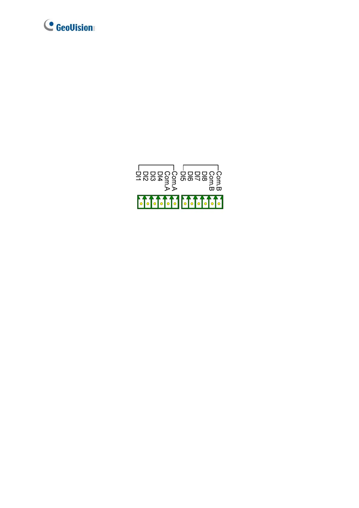
The figure below shows the pin assignments of input connectors on GV-ASBox. The 8 inputs
are divided into two terminals. Terminal A consists of DI1 to DI4, and terminal B includes DI5
to DI8. Every terminal has two COM (Common) points; connect the Common wire to any of
the two COM points on the related terminal.
Figure 9-4

Table of Contents

Other manuals for GeoVision GV-AS1010

Questions and Answers:

Question and Answer IconNeed help?

Do you have a question about the GeoVision GV-AS1010 and is the answer not in the manual?

GeoVision GV-AS1010 Specifications

General IconGeneral
BrandGeoVision
ModelGV-AS1010
CategoryController
LanguageEnglish

Related product manuals