64
3.2.1 Connecting a Wiegand Reader
GV-AS120 provides one Wiegand input for connection to the Wiegand reader ranging from
26 to 64 bits. Through the Web interface of GV-AS120, you can set the Wiegand reader as
the entry or exit reader. To define the reader, see 9.3.2.A Function Setting.
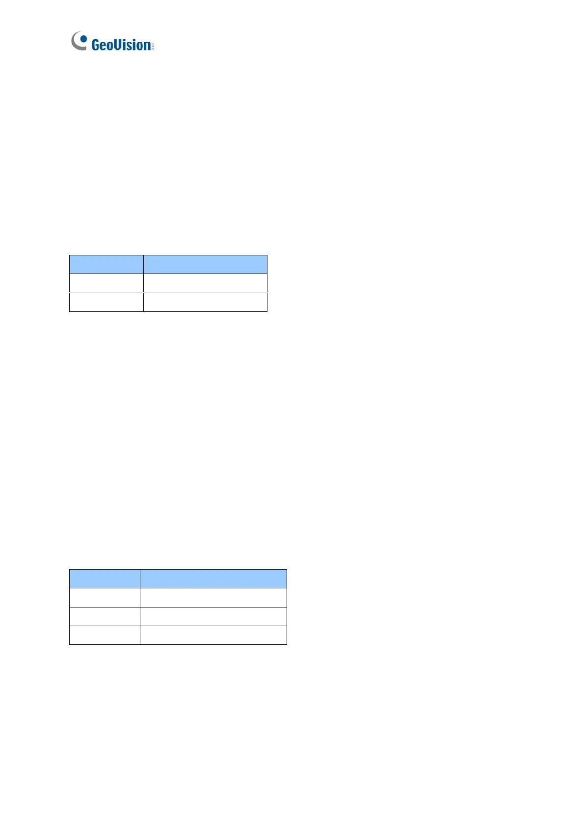
The table below shows the wire assignments of the Wiegand input on GV-AS120. Please
consult the documentation of your Wiegand reader for wiring. You will need to set up a
separate power source to power the Wiegand reader.
3.2.2 Connecting Input Devices
GV-AS120 supports 2 types of inputs:
1. Sensor inputs, e.g. door status
2. Button inputs, e.g. door opener
All inputs are dry contact and can be configured as normally open (NO) or normally closed
(NC) through the GV-AS120 Web interface. The default value is NO. To change the input
status, see 9.3.2.F In/Out Function.
The table below shows the wire assignments of input connectors on GV-AS120.
Wire color Definition
Green Wiegand Data 0
White Wiegand Date 1
Wire color Definition
Yellow Door Sensor IN1
LRed Button IN2
Brown IN COM (GND)

 Loading...


