12
1.2.3 Connecting Output Devices
GV-AS100 supports 2 types of outputs:
1. Alarm outputs, e.g. siren or bell
2. Door outputs, e.g. electronic lock
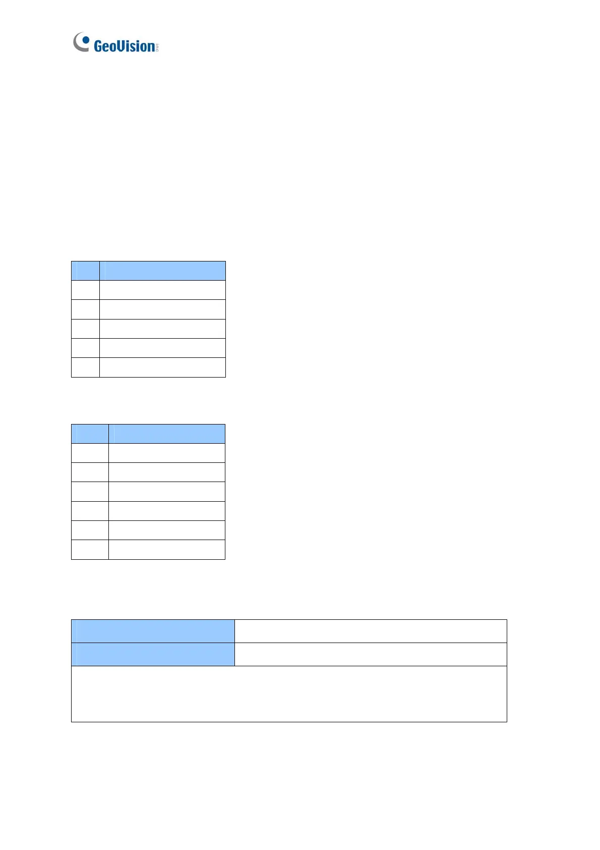
The table below shows the pin assignments of output connectors on GV-AS100 / 1010.
GV-AS100
Pin Function
15 Alarm COM
16 Alarm NO
17 Door COM
18 Door NC
19 Door NO
GV-AS1010
Pin Function
1 Door NC
2 Door NO
3 Door COM
4 Alarm NC
5 Alarm NO
6 Alarm Com
Check if your output device meets the following absolute maximum ratings before
connecting it to the Door outputs.
Breakdown Voltage
240V AC, 30V DC
Continuous Load Current
5A (NO), 3A (NC)
Note: Absolute Maximum Ratings are those values beyond which damage to GV-
AS100 circuit board may occur. Continuous operation of GV-AS100 at the absolute
rating level may affect GV-AS100 reliability.

 Loading...


