Optional Devices
173
9
9.1.4 Installation
This section describes how to connect other devices to GV-ASBox.
9.1.4.A Connecting GV-AS100 / 110 / 120
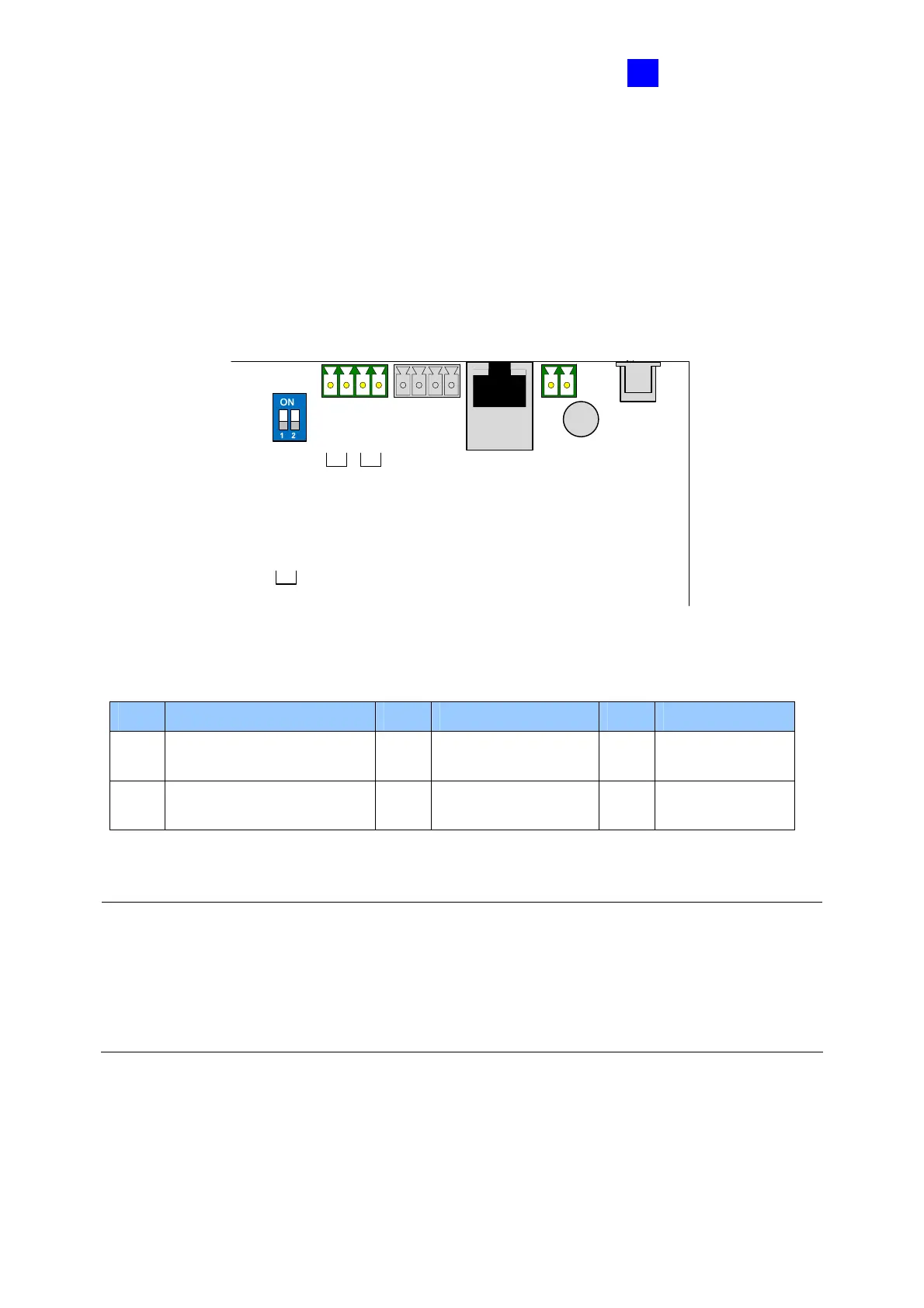
The table and figure below show the pin assignments of related connectors on GV-ASBox
for connection to GV-AS100, GV-AS110 and GV-AS120.
GND
12V
A+
A-
B+
B-
GV-AS100/110/120
GV-Readers
RS-485_A TERM
RS-485_B TERM
Figure 9-2
Pin Function Pin Function Pin Function
12V
12V Power Supply to
GV-AS100/110/120
A+
GV-AS100/110/120
Connection
B+
GV-Readers
Connection
GND
GND for Power Supply to
GV-AS100/110/120
A-
GV-AS100/110/120
Connection
B-
GV-Readers
Connection
Note:
1. By default, RS-485_A Term and RS-485_B Term are set to OFF.
2. When the distance between the GV-ASBox and the GV-AS100 / 110 / 120 is over a long
distance, RS-485_A Term must be switched to ON. When the distance between the
GV-ASBox and the GV-Readers is over a long distance, RS-485_B Term must be
switched to ON.

 Loading...


