EasyManuals Logo

GeoVision GV-AS1010 User Manual

GeoVision GV-AS1010
235 pages
To Next Page IconTo Next Page
To Previous Page IconTo Previous Page
Page #126 background imageLoading...
Page #126 background image
108
5.4.3 Connecting the GV-AS410 / 4110 / 810 / 8110 Kit
Up to 8 output devices can be powered by the power adapter board. Connect each output
device to one terminal block on the board.
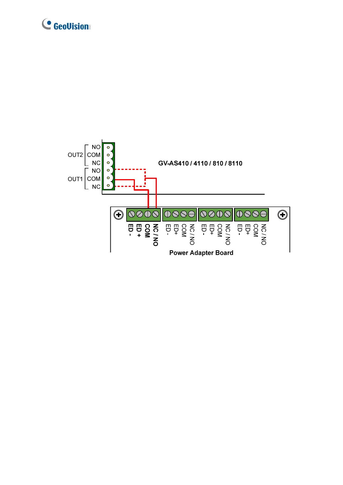
1. Connect the COM pin on GV-AS410 / 4110 / 810 / 8110’s output terminal block to the
corresponding pin on the power adapter board. Connect the NC / NO pins according to
the state of the output device.
Figure 5-13

Table of Contents

Other manuals for GeoVision GV-AS1010

Questions and Answers:

Question and Answer IconNeed help?

Do you have a question about the GeoVision GV-AS1010 and is the answer not in the manual?

GeoVision GV-AS1010 Specifications

General IconGeneral
BrandGeoVision
ModelGV-AS1010
CategoryController
LanguageEnglish

Related product manuals