EasyManuals Logo

GeoVision GV-AS1010 User Manual

GeoVision GV-AS1010
235 pages
To Next Page IconTo Next Page
To Previous Page IconTo Previous Page
Page #99 background imageLoading...
Page #99 background image
GV-AS210 / 2110 / 2120 Controller
81
4
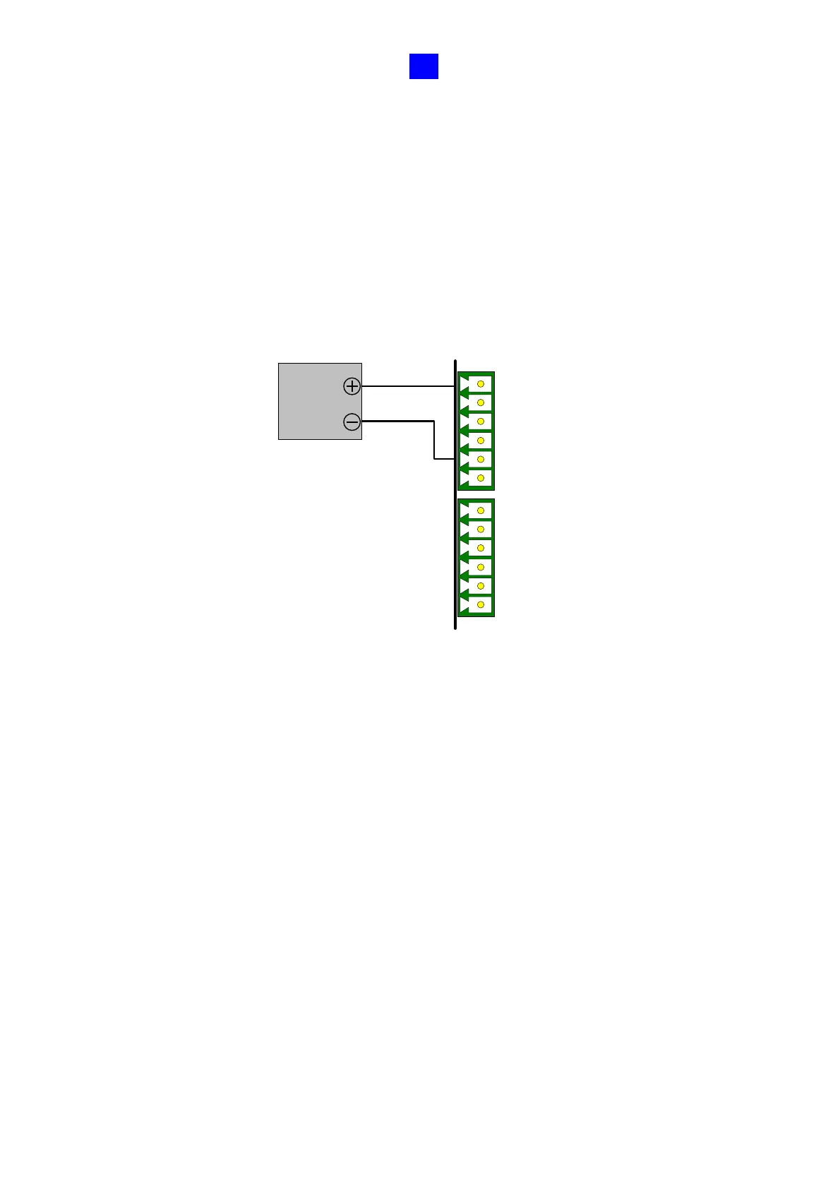
4.2.2 Connecting Input Devices
Up to 8 input devices can be connected to GV-AS210 / 2110 / 2120. Connect the input wires
to DI1~8 and connect GND wires to com.A or com.B. Multiple GND wires can be connected
to the same com.A/B interface.
All inputs are dry contact that can be configured as normally open (NO) or normally closed
(NC) on the Web interface. To change the input status, refer to 8.2.6 Input Configuration.
DI1
DI2
DI3
DI4
com.A
com.A
DI5
DI6
DI7
DI8
com.B
com.B
Input
Device
GND
IN
Figure 4-5

Table of Contents

Other manuals for GeoVision GV-AS1010

Questions and Answers:

Question and Answer IconNeed help?

Do you have a question about the GeoVision GV-AS1010 and is the answer not in the manual?

GeoVision GV-AS1010 Specifications

General IconGeneral
BrandGeoVision
ModelGV-AS1010
CategoryController
LanguageEnglish

Related product manuals