16
Network Connection between GV-AS100 and PC
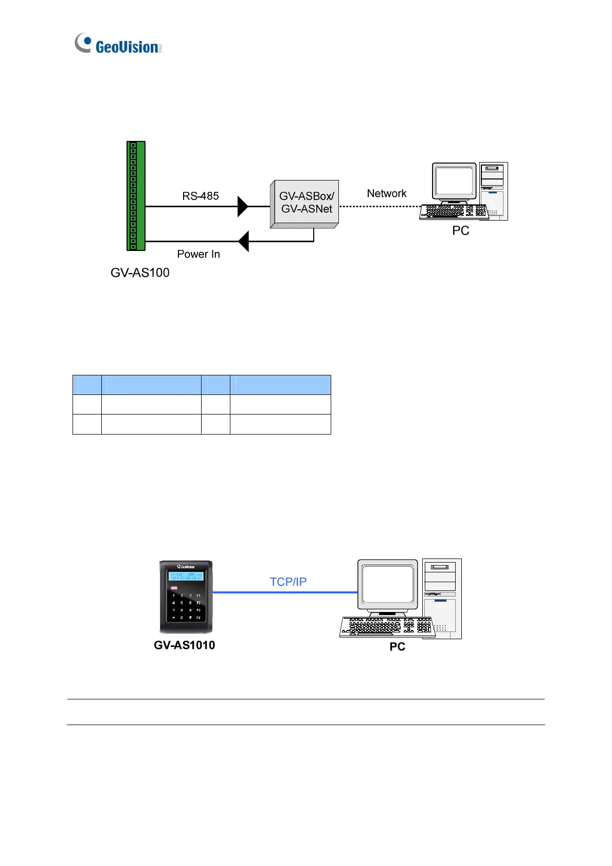
The figure below illustrates the network connection to the computer. For this connection, the
optional product GV-ASBox or GV-ASNet is required.
Figure 1-11
Connect two power wires and two RS-485 wires from GV-ASBox / GV-ASNet to GV-AS100.
The table below shows the pin assignments of related connectors on GV-AS100.
Pin Function Pin Function
1 Power In 12V 3 RS-485 A+
2 GND 4 RS-485 A-
Also see 9.1.4.A Connecting GV-AS100 / 110 / 120.
1.2.4.B Connecting GV-AS1010 to PC
The figure below illustrates the network connection between GV-AS1010 and the computer.
Figure 1-12
Note: GV-AS1010 is only compatible with GV-ASManager V4.2.3 or later.

 Loading...


