GV-AS110 / 1110 Controller
43
2
2.2.3 Connecting Output Devices
GV-AS110 supports 2 types of outputs, while GV-AS1110 supports 1 type of output:
1. GV-AS110 only: Alarm outputs, e.g. siren or bell
2. GV-AS110 / 1110: Door outputs, e.g. electronic lock
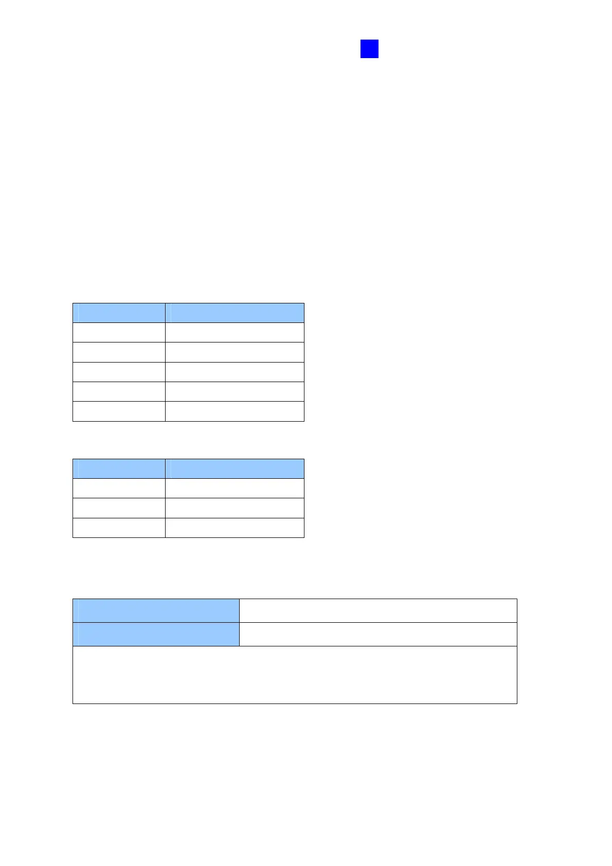
The table below shows the wire assignments of output connectors on GV-AS110 and GV-
AS1110.
GV-AS110
Wire color Definition
Purple Alarm COM
Gray Alarm NO
Brown & White Door COM
Black & White Door NC
Light green Door NO
GV-AS1110
Wire color Definition
Brown Door A Com
Yellow Door A NC
Orange Door A NO
Check if your output device meets the following absolute maximum ratings before
connecting it to the Door outputs.
Breakdown Voltage
250V AC, 220V DC
Continuous Load Current
1A (30V DC), 0.3A (125V AC)
Note: Absolute Maximum Ratings are those values beyond which damage to GV-
AS110 / 1110 circuit board may occur. Continuous operation of GV-AS110 at the
absolute rating level may affect GV-AS110 / 1110’s reliability.

 Loading...


