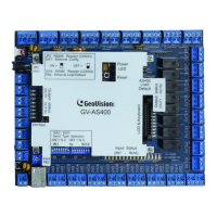
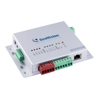
GV-AS100 / 1010 Controller
17
1
1.2.4.C Switches (GV-AS100 Only)
Switch 1: When Switch 1 is ON, GV-AS100 can connect to GV-ASManager, GV-ASBox or
GV-ASNet. When Switch 1 is OFF, the connection is unavailable. By default Switch 1 is set
to ON.
Switch 2: When the RS-485 connection between GV-AS100 and computer is over a long
distance, the RS-485 signal may become weak. In this case, turn Switch 2 ON to have a
120-Ohm resistor.
Figure 1-13
1.2.5 Connecting the Power
The supplied power adaptor can be connected to any power source supplying from 100 to
240V. Using the supplied power cord and adaptor, connect GV-AS100 / 1010 to the power.
Note: Power should only be applied to the unit when all connections are completed and
tested.

 Loading...


