GV-AS100 / 1010 Controller
13
1
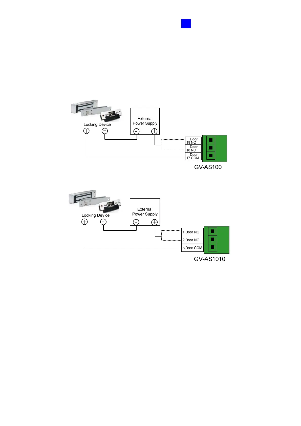
To connect an output device:
The example below illustrates the connection of a locking device to GV-AS100 / 1010.
Connect the (+) point on the locking device to the Door COM on GV-AS100 / 1010, connect
the two (-) points of the locking device and the external power supply together, and connect
the (+) point on the external power supply to the Door NO or Door NC on GV-AS100 / 1010
based on the state of the locking device.
Figure 1-9

 Loading...


