2.2 Screen Names and Configurations
14
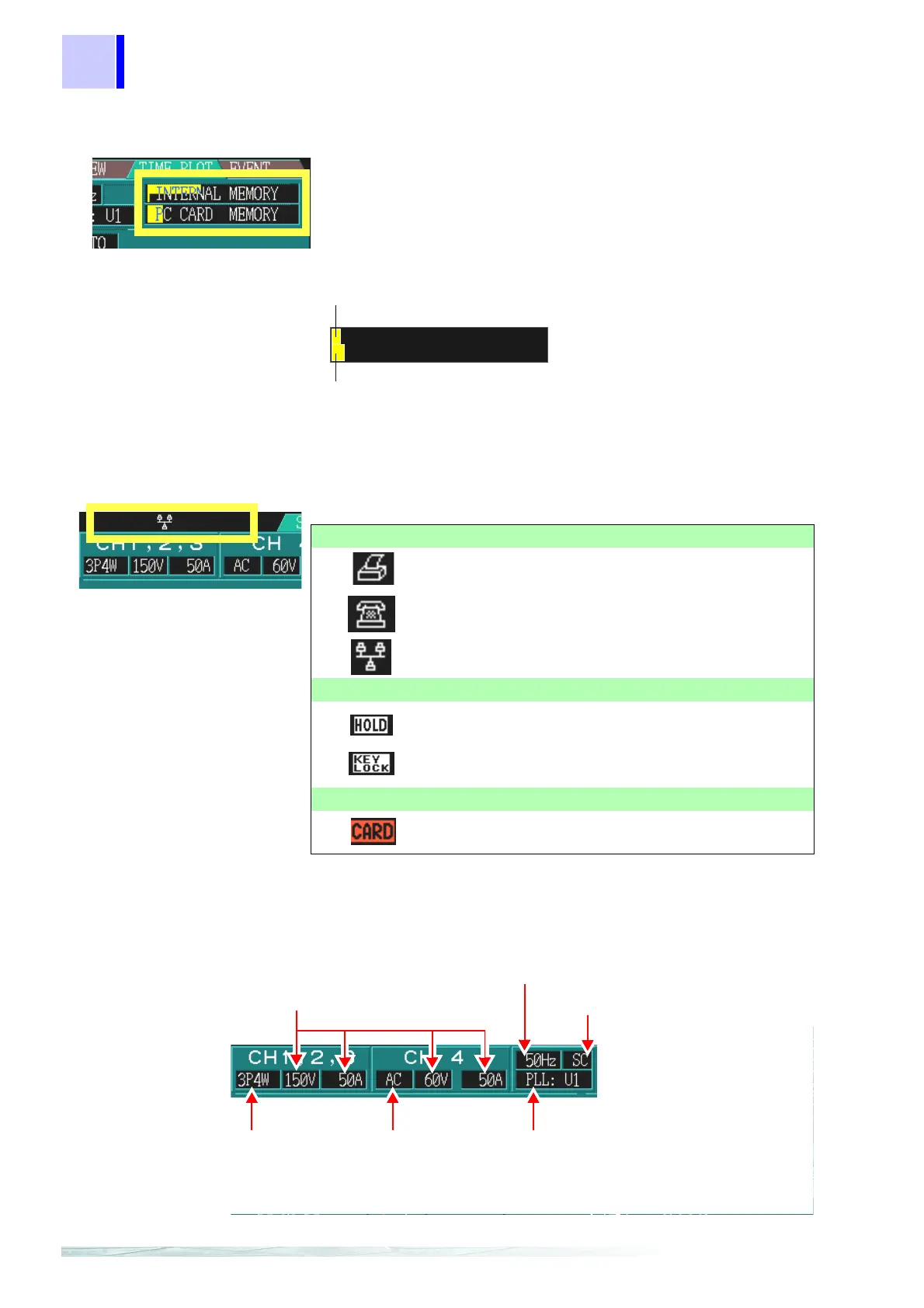
*3:Memory Usage Indicators
*4:Status Icons
*5: SYSTEM settings display
INTERNAL MEMORY: Internal memory
PC CARD MEMORY: ATA flash card
INTERNAL MEMORY
TIME PLOT related data capacity
Measurement stops when memory becomes full.
(Selectable Stop/Continuous)
Up to 100 EVENT data sets can be stored
After 100 events are stored, the earliest are overwritten.
Total capacity: 5 MB
Total capacity: 8 MB
Interface usage status indicators
Indicates the printer is ready for use.
Indicates the modem is ready for use.
Indicates the LAN interface is ready for use.
HOLD/LOCK status indicators
Indicates the
DATA HOLD key has been pressed to
activate the Data Hold function.
Indicates the
KEY LOCK switch has set to lock the
keys.
PC card status display
Lights when the PC Card is being accessed.
Measurement Line type
Set on the SYSTEM screen
Voltage/Current Range
Red Indication: means out of range
In this case, increase the range set-
ting.
Frequency of Measured
Line
Red Indication: means the mea-
surement frequency is different
from the line frequency
PLL Sync Frequency source
Indicates red when no input is applied at the
selected source.
CH4 Voltage measure-
ment function
(AC/ DC/OFF)
PT(VT)/CT Ratio
[SC] (scaling):Appears when the PT
or CT ratio has been set.
[(Not displayed)]: when the PT and
CT ratios are both 1.