12.4 Formulae
203
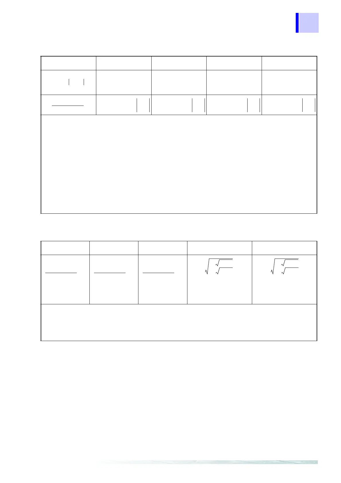
Displacement power factor DPF
Single-phase 2-wire
1P2W
Single-phase 3-wire
1P3W
Three-phase 3-wire
3P3W2M
Three-phase 3-wire
3P3W3M
Three-phase 4-wire
3P4W
DPF1 DPF1
DPF2
DPF1
DPF2
DPF1
DPF2
DPF3
DPF1
DPF2
DPF3
• The polarity symbol si of power factors indicates a LEAD or LAG in polarity; no symbol indicates a LAG,
while the “-” symbol indicates a LEAD.
• Calculate the harmonic reactive power using the polarity symbol sic and attach the symbol for the funda-
mental wave reactive power (using k = 1 (1st order) for each measured channel (c)).
• Calculate the harmonic reactive power using the polarity symbol sisum and attach the opposite symbol for
the sum of the fundamental wave reactive power (using k = 1 (1st order)). (See the harmonic reactive
power formula.(page 206))
• θc1 indicates the voltage-current phase difference for the fundamental wave. (See the voltage-current
phase difference formula.(page 209))
• Psum1 indicates the total of fundamental wave power and the formula becomes k = 1 for the sum of har-
monic power. (See the harmonic power formula.(page 206))
• Ssum1 indicates the total of fundamental wave apparent power and can be searched for using the funda-
mental wave RMS voltage and fundamental wave RMS current. (For information on the formulae for har-
monic voltage, harmonic current, and the sum of apparent power, see (page 204).)
c: measured channel, k: order for analysis
DPFc sic θc1cos=
PFsum sisum
P
sum
Ssum
-------
=
PFsum sisum
P
sum
Ssum
--------
=
PFsum sisum
P
sum
Ssum
--------
=
PFsum sisum
P
sum
Ssum
--------
=
Voltage unbalance factor Uunb (%)
Single-phase 2-wire
1P2W
Single-phase 3-wire
1P3W
Three-phase 3-wire
3P3W2M
Three-phase 3-wire
3P3W3M
Three-phase 4-wire
3P4W
•For U12, U23, and U31, use the fundamental wave RMS voltage from the calculated harmonics results.
• Calculate the Discrete Fourier Transform of the harmonic RMS voltage at 2048 points (about once every
10 cycles at 50 Hz or every 12 cycles at 60 Hz).
• For three-phase 4-wire configurations, this is detected using phase-to-neutral voltage but can be con-
verted and calculated using line-to-line voltage.
unb
136β––
136β–+
---------------------- 100×=
β
U
4
12
U
4
23
U
4
31
++
U
2
12
U
2
23
U
2
31
++()
2
-------------------------------------
=
Uunb
136β––
136β–+
---------------------- 100×=
β
U
4
12
U
4
23
U
4
31
++
U
2
12
U
2
23
U
2
31
++()
2
-------------------------------------
=