12.4 Formulae
210
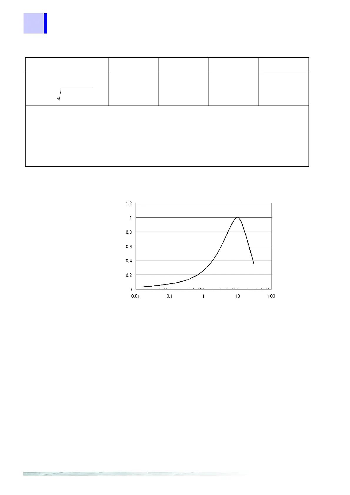
ΔV10 Perceived flicker curve
Voltage flicker ΔV10 (V)
Single-phase 2-wire
1P2W
Single-phase 3-wire
1P3W
Three-phase 3-wire
3P3W2M
Three-phase 3-wire
3P3W3M
Three-phase 4-wire
3P4W
Δ
V10(1)
Δ
V10(2)
Δ
V10(12)
Δ
V10(32)
Δ
V10(12)
Δ
V10(23)
Δ
V10(31)
Δ
V10(1)
Δ
V10(2)
Δ
V10(3)
• Ur is the basic voltage for the change in voltage and Uf is the basic voltage for the voltage flicker, and they
both operate automatically.
• Ur indicates the value passing through the primary LPF (for a response time of 1 m) and Uf indicates the
average RMS voltage over a 1-minute interval.
•
an is the flicker luminosity coefficient corresponding to the change in frequency fn (Hz) that can be
detected from the flicker luminosity curve.
•
ΔUn is the change in voltage for fn.
• For connections other than single-phase two-wire, you can select any
ΔV10 value for calculation.
c: measured channel
ΔV10 c()
100
U
f
--------- an ΔUn×()
2
∑
=
ΔV10 1()
Frequency[Hz]
ΔV10
Perceived flicker coefficient