WEPT
ELI
GENERRTOR
HP 4378
POUER
METER
POUER SENSOR
SUJRCE
MODULE
I
I
FF
OUT
INTERFACE
DUT
IIll-URVE
SOURCE
-m
-------
SUEPT
CU
GENERATOR
HP 4378
POWER
flEfER
NICROUAVE
RNPLIFIER
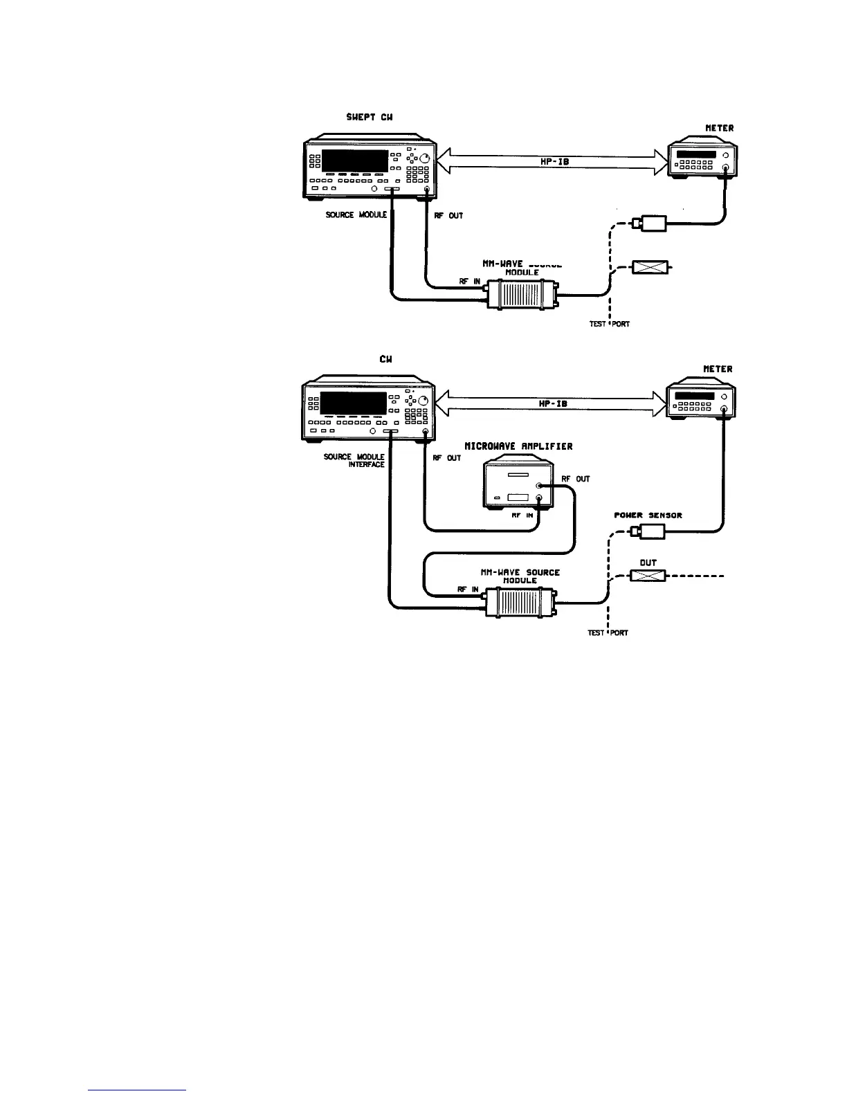
Figure l-20.
Creating Arbitrarily Spaced Frequency-Correction Pairs in a Swept mm-wave
Environment
For this example, refer to menu map 5, POWER.
1. The equipment setup shown in Figure l-20 assumes that
you have followed the steps necessary to correctly level the
configuration. If you have questions about external leveling, refer
to “Externally Leveling the Swept CW Generator”.
Set up Power Meter
2. Zero and calibrate the power meter/sensor.
3. Connect the power sensor to test port.
4. Enter and store in the power meter, the power sensor’s cal factors
for correction frequencies to be used.
l-40 Getting Started Advanced

 Loading...


