CONNECTORS
MOD Cl
+5V
MOD
ANLG
GND
MODMOD
SENSESENSE
MOD
Gl
MOD Dl DIG
&D
DIG
-iiND
MT
LVL’(COAX)
\
MT
LVL’
(COAX)
\
-15v-15v
REiEKV?DRESEWED
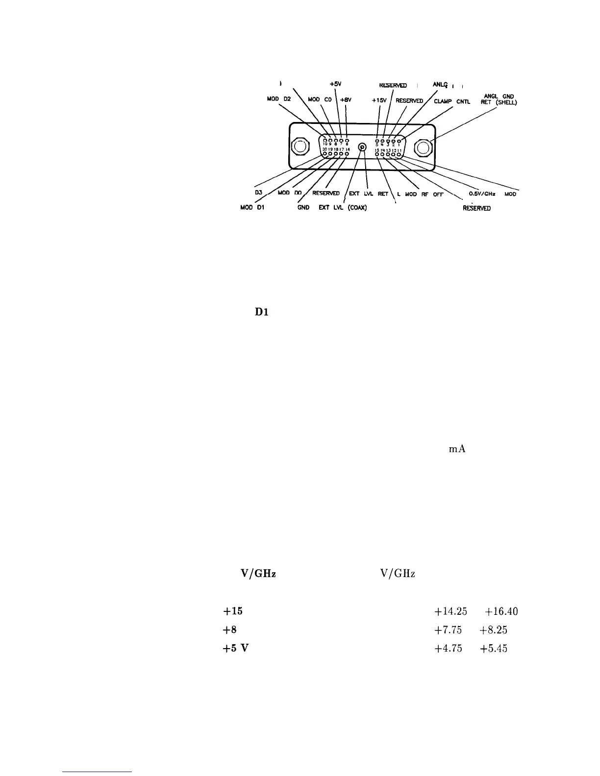
Figure C-3. Interface Signals of the Source Module ConnectorFigure C-3. Interface Signals of the Source Module Connector
The codes indicated on the illustration above translate as follows:
The codes indicated on the illustration above translate as follows:
MOD DO
Source module data line zero. Signals MOD DO
through MOD D3 are the mm source module
data bus lines (bi-directional).
Data line one.
MOD
Dl
MOD D2
MOD D3
MOD CO
MOD Cl
CLAMP CNTL
MOD SENSE
L MOD RF OFF
EXT LVL RET
EXT LVL
0.5
V/GHz
-15 v
+15
v
+a
v
+5
v
DIG GND
MOD ANLG GND
ANLG GND RET
Data line two.
Data line three.
Source module control line zero. Signals MOD
CO and MOD Cl are the control lines for the
read/write to and from the mm source module.
Control line one.
Source module clamp control (not used).
Source module sense. A 1 mA current is
injected on this line by the mm source module
to indicate its presence. This signal always
equals 0 V.
Low = RF off. Source module RF is turned off.
Source module external leveling return.
Source module external leveling input, from the
mm source module.
Internal 0.5
V/GHz
to the mm source module.
Power supply. Range is -14.25 to -15.90 V.
Power supply. Range is +14.25 to
+16.40
V
Power supply. Range is
f7.75
to
+8.25
V.
Power supply. Range is
+4.75
to
+5.45
V.
Digital ground.
Source module analog ground.
Analog ground return.
Operating and Programming Reference C-9

 Loading...


