LED Indicators, Switches, and Jumpers
LEDs
A variety of LEDs are located on the front and back of the server. These LEDs aid
you in diagnosing problems by communicating the status of the components and
operations of the server. The following LEDs specific to the server are explained in
this appendix:
Server LEDs (on the front of the server) ·
·
·
·
·
·
·
·
·
·
System board LEDs
Network controller LEDs (on the back of the server)
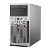
Server LEDs
The server LEDs and the power button are located on the front of the server.
The server LEDs show the following:
Power On/Standby status
Hard drive activity
Health status
NIC link/activity status
The power button allows you to:
Power up the server (provide AC power)
Place the server in standby mode
Power down the server
E-2 HP ProLiant ML310 Server Setup and Installation Guide
HP CONFIDENTIAL
Writer: Ted Weiman File Name: l-appe.doc
Codename: Son of Beast Part Number: 274431-002 Last Saved On: 11/22/02 2:10 PM