Torch Connect Console
XPR300 Field Service Bulletin 809970 103
Replace the control PCB
See Torch connect console manifold side – view 1 on page 141 for
location and part number.
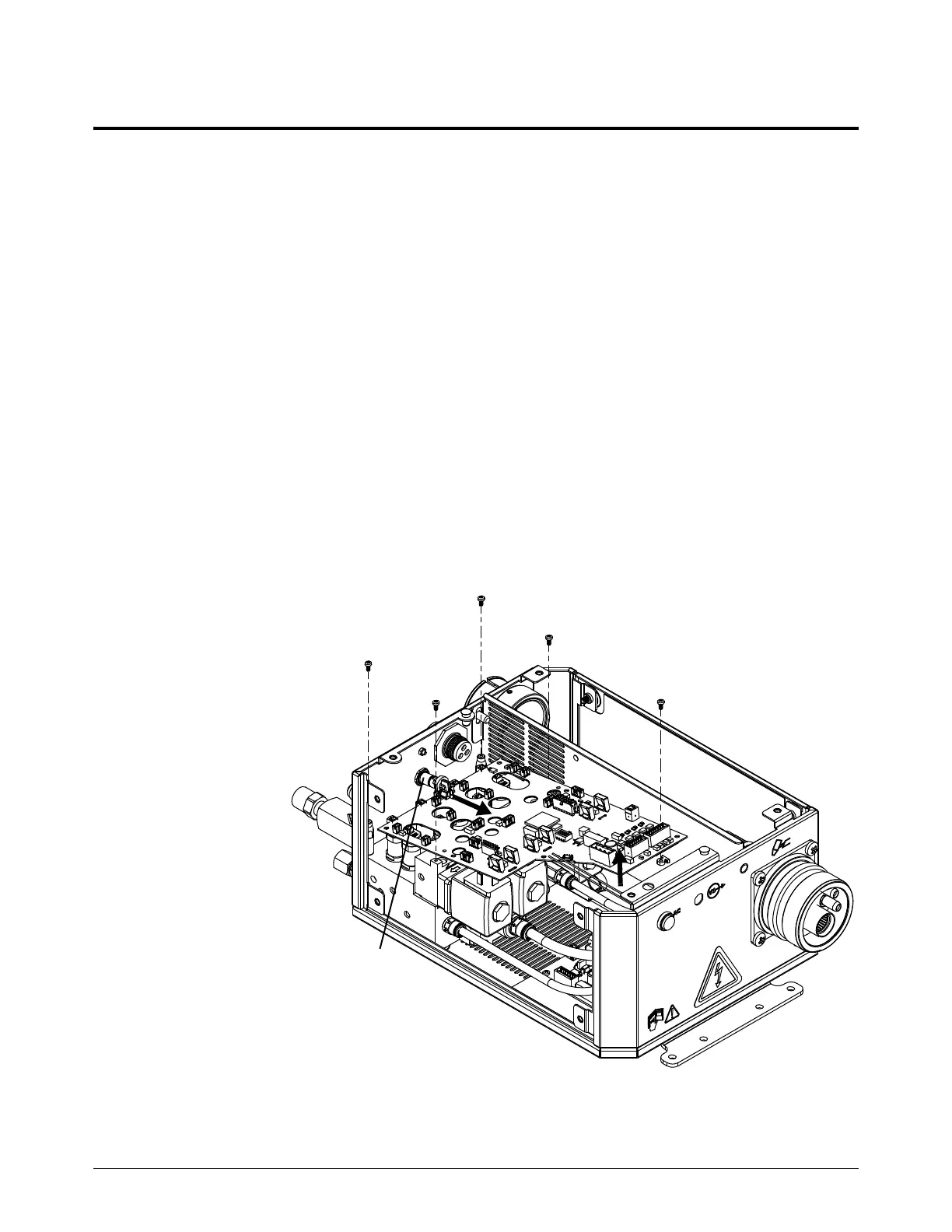
Remove the control PCB
1. Complete the following procedures:
a. Remove the power from the cutting system.
b. Remove the gas pressure from the cutting system.
c. Remove the top panel.
d. Remove the control-side panel.
See Torch connect console top panel and side panels on page 114.
Keep all nuts and screws that you remove.
2. Disconnect and remove the pressure transducers. See Replace a pressure transducer on
page 95.
3. Disconnect all
of the wires
from the PCB.
4. Remove the 5
screws from
the PCB.
5. Tilt the end of
the PCB up
and pull the
PCB out.