Plasma Power Supply
46 809970 Field Service Bulletin XPR300
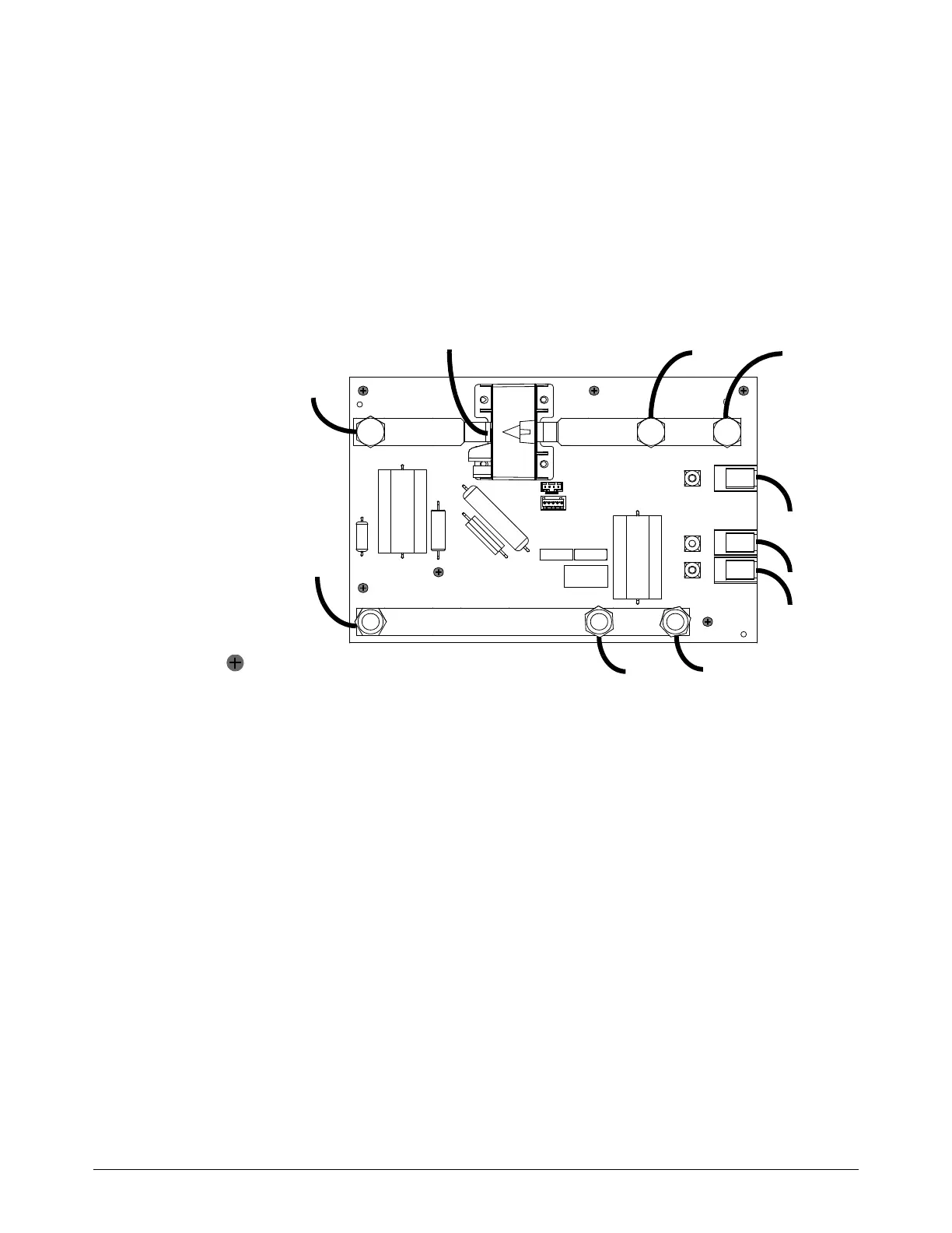
Replace the I/O PCB
See Control side – view 2 on page 127 for location and part number.
1. Complete the following procedures:
a. Remove the power from the cutting system.
b. See Remove the left-side (control-side) panel on page 61.
Keep all nuts and screws that you remove.
2. Disconnect
HRS39, HRS40,
HRS3, and J5.
3. Use an 17 mm,
hexagonal-socket
wrench to remove
J2.1, J39.2, J39.3,
4. Use a 17 mm,
hexagonal-socket
wrench to remove
J1.1, J1.4, and
J1.5.
5. Remove the 6
screws .
6. Use the 6 screws to install the new I/O PCB.
7. Apply thread locker to the threads.
8. Use a 17 mm, hexagonal-socket wrench to install J1.1, J1.4, and J1.5. Tighten to 13 N∙m
(115 in∙lb).
9. Use an 17 mm, hexagonal-socket wrench to install J2.1, J39.2, and J39.3. Tighten to 13 N∙m
(115 in∙lb).
10. Connect HRS39, HRS40, HRS3, and J5.
11 . Install the control-side panel.
J2.1
J1.1
HRS39
HRS40
HRS3
J1.4
J1.5
J39.3
J39.2J5