Plasma Power Supply
48 809970 Field Service Bulletin XPR300
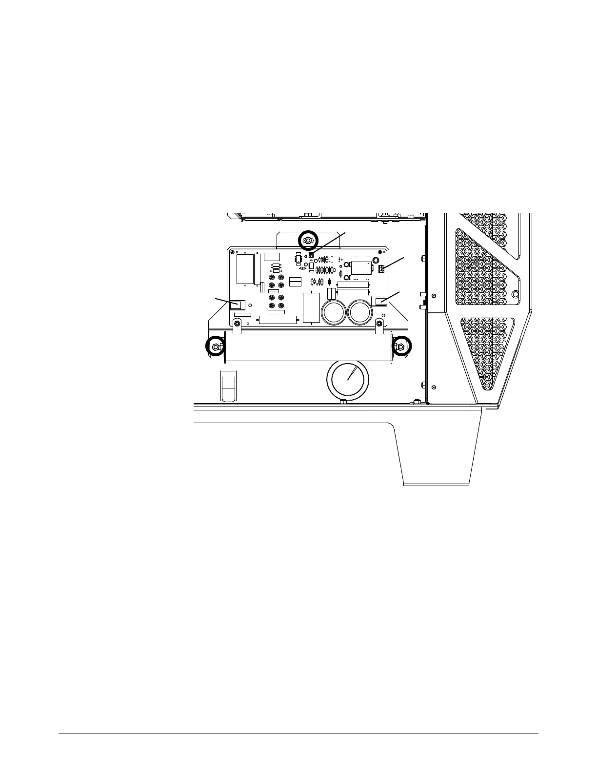
Replace start circuit assembly
See Control side – view 1 on page 126 for location and part number.
1. Complete the following procedures:
a. Remove the power from the cutting system.
b. See Remove the left-side (control-side) panel on page 61.
Keep all nuts and screws that you remove.
2. Disconnect J4,
J6, J7, and J8.
3. Use a 10 mm,
hexagonal-socket
wrench to
remove the 3
nuts.
4. Pull the assembly
straight out.
5. Align the heatsink
of the new PCB
with the hole in
the sheet metal.
6. Align the new
PCB with the
mounting studs.
7. Install the 3 nuts.
Tighten to 9 N∙m
(80 in∙lb).
8. Connect J4, J6, J7, and J8.
9. Install the control-side panel.