Plasma Power Supply
44 809970 Field Service Bulletin XPR300
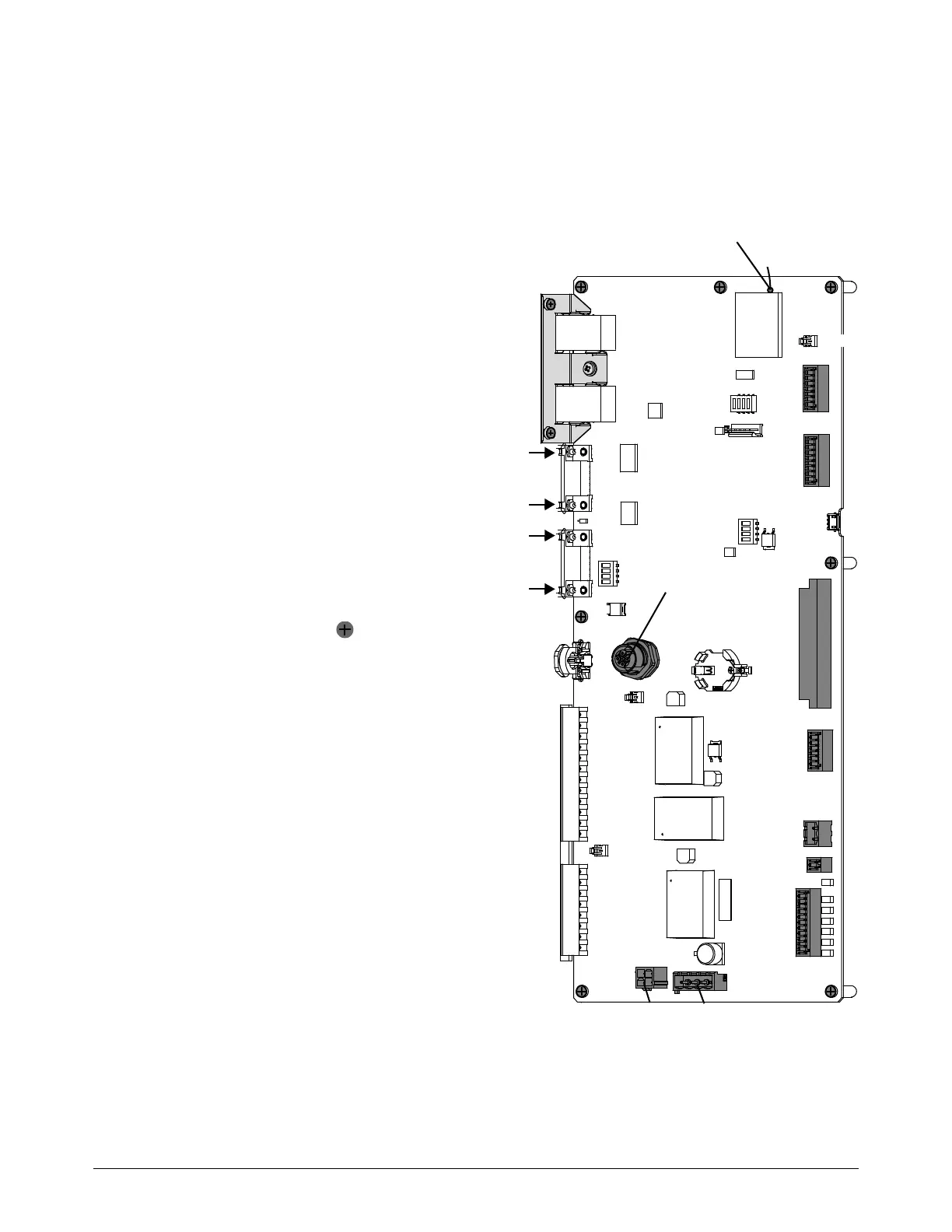
Replace the control PCB
See Control side – view 2 on page 127 for location and part number.
1. Complete the following procedures:
a. Remove the power from the cutting
system.
b. See Remove the left-side
(control-side) panel on page 61.
c. See Remove the rear panel on
page 62.
Keep all nuts and screws that
you remove.
2. Disconnect the communication interface
cables. (discrete, serial, or EtherCAT)
3. Disconnect all of the wire connectors.
4. Use a 3/16 inch, hexagonal-socket
wrench to remove the 4 nuts from the
serial RS-422 connectors.
5. Remove the 9 screws.
6. Move the PCB to the right to release the
PCB from the external CAN connector.
7. Use the screws to install the new PCB.
8. Use a 3/16 inch, hexagonal-socket
wrench to install nuts on the serial
RS-422 connectors on the rear panel
side.
9. Make sure that J21 is in the OFF
position.
10. Connect all of the wire connectors.
11 . Connect the communication interface
cables.
Make sure that you connect the
in and out cables to the correct
locations.
J4
Out
J7
J8
J23
J16
J6
J1J5
Wireless antenna
CAN
In
J2
J21