Gas Connect Consoles
XPR300 Field Service Bulletin 809970 75
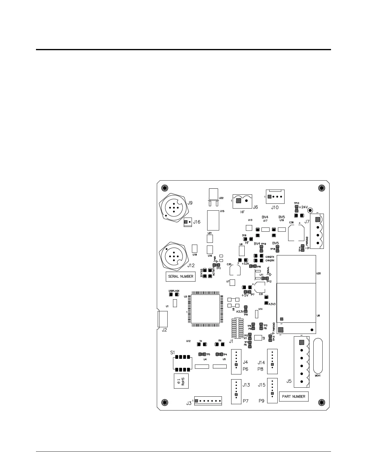
Replace the control PCB
See Core, VWI, and OptiMix gas connect console manifold side on
page 131 for location and part number.
1. Complete the following procedures:
a. Remove the power from the cutting system.
b. Remove the top panel.
c. Remove the manifold-side panel.
See Gas connect console panels on page 87.
Keep all nuts and screws that you remove.
2. Disconnect all of the wire
connectors.
3. Use a T15 driver to remove
the 4 screws.
4. Use the 4 screws to install
the PCB.
5. Connect the wire connectors
to the PCB.
Make sure that the
pressure transducer
wires goes to the
correct pressure
transducer
connector.
6. Install the manifold-side
panel.
7. Install the top panel.
D18
D17
D16
D30
D1
D5
D6
D31
D25
D29
D15
D26
D24