Torch Connect Console
XPR300 Field Service Bulletin 809970 111
Replace the bottom manifold assembly
See Torch connect console manifold side – view 2 on page 142 for
location and part number.
Remove the bottom manifold assembly
1. Complete the following procedures:
a. Remove the power from the cutting system.
b. Remove the gas pressure from the cutting system.
c. Drain the coolant. See Remove old coolant from the coolant system in the Maintenance
section in the XPR300 Instruction Manual (809480).
d. Remove the top panel.
e. Remove the side panels.
See Torch connect console top panel and side panels on page 114.
Keep all nuts and screws that you remove.
2. Remove the gas supply hoses.
3. Remove the ohmic relay and bracket. See Remove the ohmic relay
and bracket on page 93.
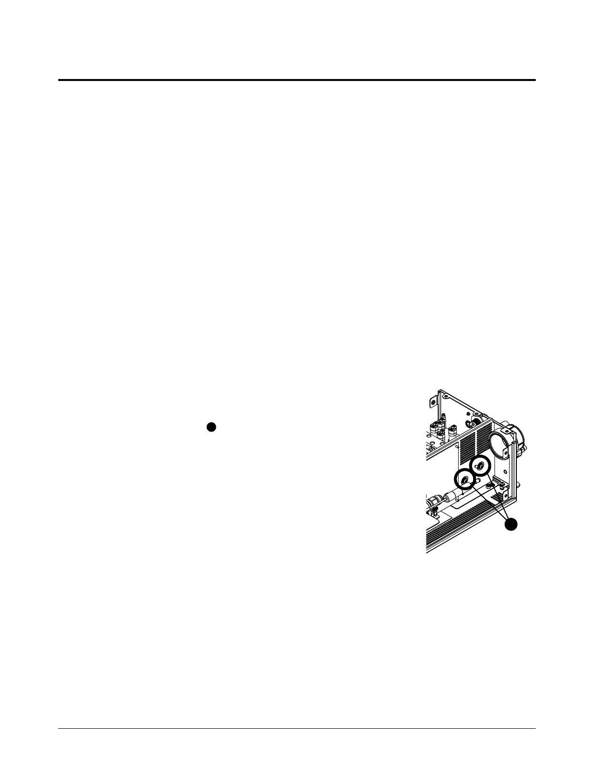
4. Remove the 2 screws that hold the manifold assembly in from the
side.
5. Remove the power connector (J19), ohmic board connector (J27) and
V1 connector (J7) from the control PCB.