Plasma Power Supply
26 809970 Field Service Bulletin XPR300
Replace the fan power distribution PCB
See Fans on page 121 for location and part number.
1. Complete the following procedures:
a. Remove the power from the cutting system.
b. See Remove the right-side (liquid-cooling-side) panel on page 60.
Keep all nuts and screws that you remove.
2. Disconnect all of the wire connectors.
3. Remove 2 screws from the bottom of the PCB.
4. Pull the PCB off of the 2 push connectors.
5. Align the new PCB with the studs and push it in until you
hear a click.
6. Install the 2 screws.
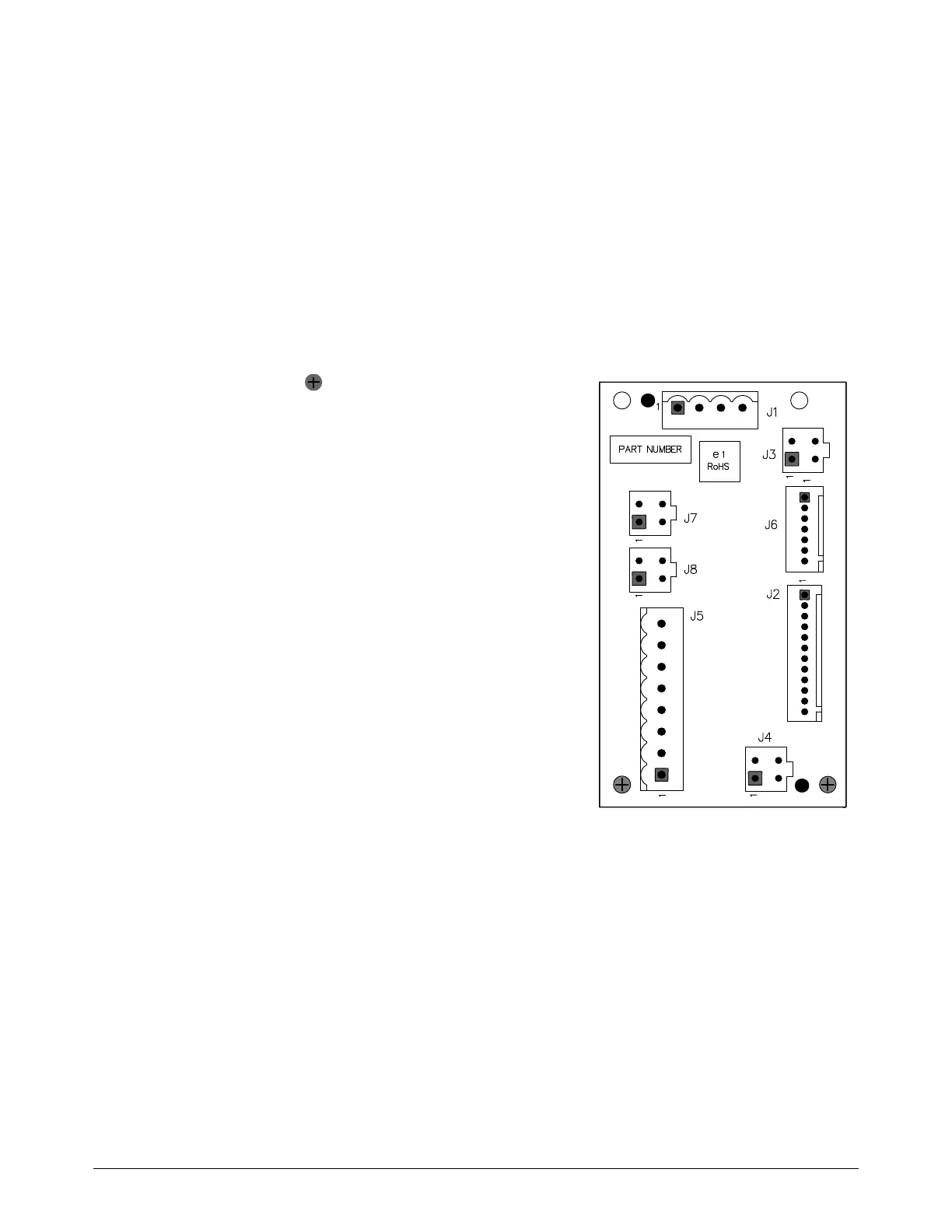
7. Connect the wires:
J1 for the 48 V power source
J2 for the control PCB
J3 for the top heat-exchanger fan
J4 for the bottom heat-exchanger fan
J5 for the magnetics fan
J6 for the control PCB
J7 for the top control-side fan
J8 for the bottom control-side fan
8. Install the right-side (liquid-cooling-side) panel.