EasyManuals Logo

Hypertherm XPR300 Replacement Part Procedures

Hypertherm XPR300
162 pages
To Next Page IconTo Next Page
To Previous Page IconTo Previous Page
Page #142 background imageLoading...
Page #142 background image
Parts List
5
142 809970 Instruction Manual XPR300
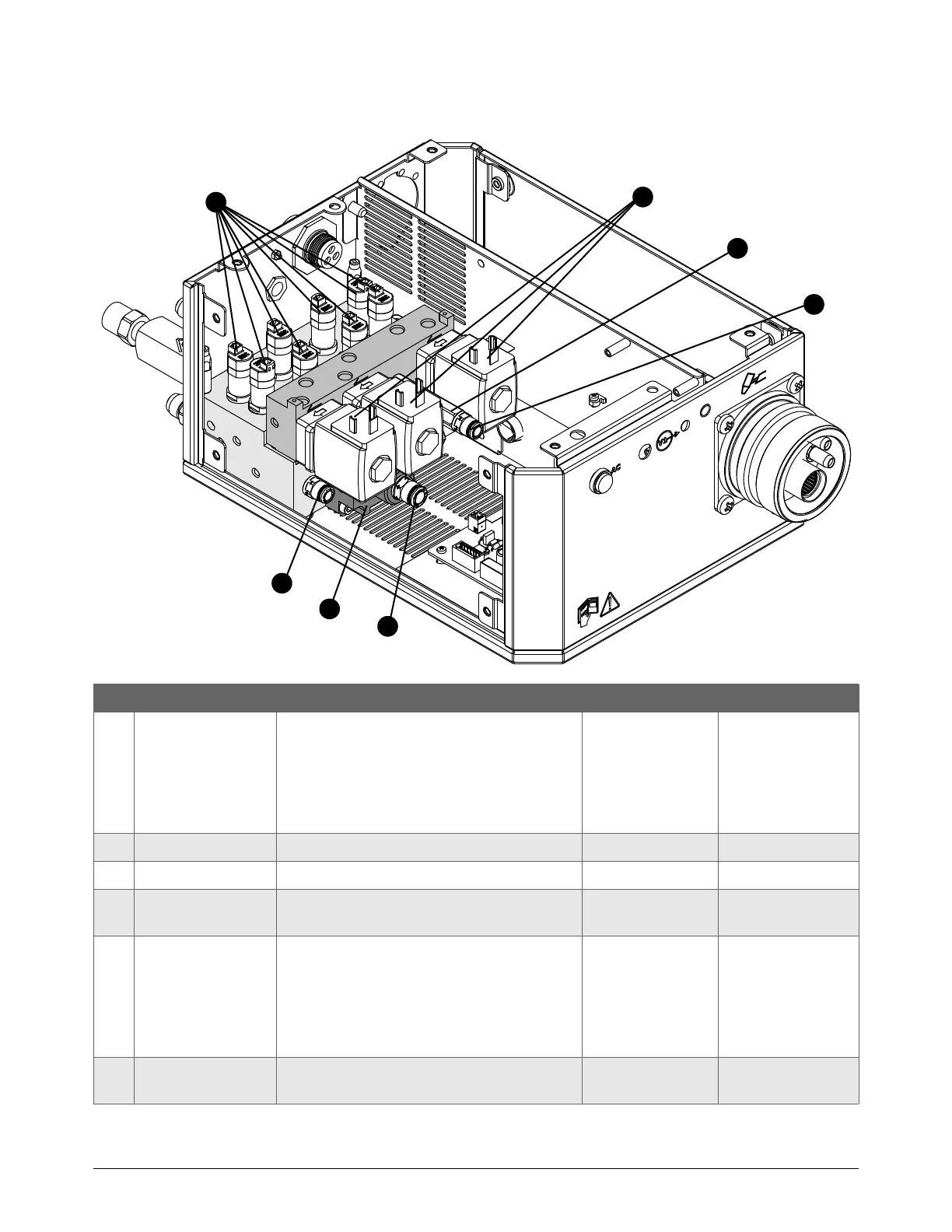
Torch connect console manifold side – view 2
Part number Description Designator Quantity
229895 Manifold assembly:
Solenoid valves
Proportional valves
All manifolds
All fittings
–1
1 229965 Solenoid valve V4 – V12 9 (8 shown)
229917 Solenoid valve (229965) tool
2
015905 Adapter: 1/8 inch NPT O-ring seal X
1/4 inch tube
2
3
428756 Bottom manifold assembly:
Bottom manifold
•Adapter
Critical orifice
Solenoid valve
–1
4
015811 Adapter: 1/4 inch NPT O-ring seal X 8 mm
tube
1
1
2
3
4
5
6
2

Table of Contents

Other manuals for Hypertherm XPR300

Questions and Answers:

Question and Answer IconNeed help?

Do you have a question about the Hypertherm XPR300 and is the answer not in the manual?

Hypertherm XPR300 Specifications

General IconGeneral
Cutting Current300 A
Duty Cycle100% at 300 A
TechnologyX-Definition Plasma
Gas SupplyOxygen, Nitrogen, Air
Cutting Capacity (Mild Steel)38 mm (1.5 in)
Severance Capacity (Mild Steel)75 mm (3 in)
Pierce Capacity (Mild Steel)50 mm (2 in)
Input Voltage200–480 V, 3-PH, 50/60 Hz

Related product manuals