EasyManuals Logo

Hypertherm XPR300 Replacement Part Procedures

Hypertherm XPR300
162 pages
To Next Page IconTo Next Page
To Previous Page IconTo Previous Page
Page #49 background imageLoading...
Page #49 background image
Plasma Power Supply
1
XPR300 Field Service Bulletin 809970 49
Bottom-compartment parts
Replace an inductor
See Transformers and inductors on page 125 for location and part
number.
Remove an inductor
1. Complete the following procedures:
a. Remove the power from the cutting system.
b. See Remove the right-side (liquid-cooling-side) panel on page 60.
c. See Remove the front panel on page 59.
Keep all nuts and screws that you remove.
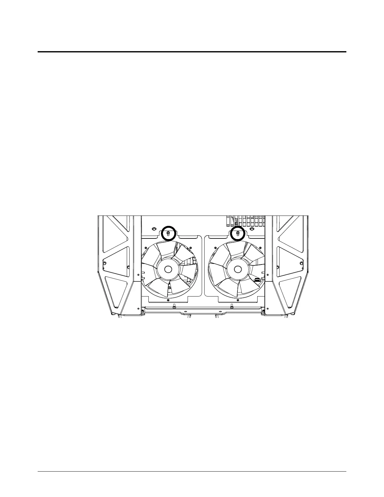
2. Use a 10 mm, hexagonal-socket wrench to remove the nut from the top of the fan bracket.
3. Tilt the top of the bracket towards you until you get access to the fan-wire connector.
4. Disconnect the fan-wire connector.
5. Remove the fan and bracket assembly.

Table of Contents

Other manuals for Hypertherm XPR300

Questions and Answers:

Question and Answer IconNeed help?

Do you have a question about the Hypertherm XPR300 and is the answer not in the manual?

Hypertherm XPR300 Specifications

General IconGeneral
Cutting Current300 A
Duty Cycle100% at 300 A
TechnologyX-Definition Plasma
Gas SupplyOxygen, Nitrogen, Air
Cutting Capacity (Mild Steel)38 mm (1.5 in)
Severance Capacity (Mild Steel)75 mm (3 in)
Pierce Capacity (Mild Steel)50 mm (2 in)
Input Voltage200–480 V, 3-PH, 50/60 Hz

Related product manuals