Torch Connect Console
XPR300 Field Service Bulletin 809970 101
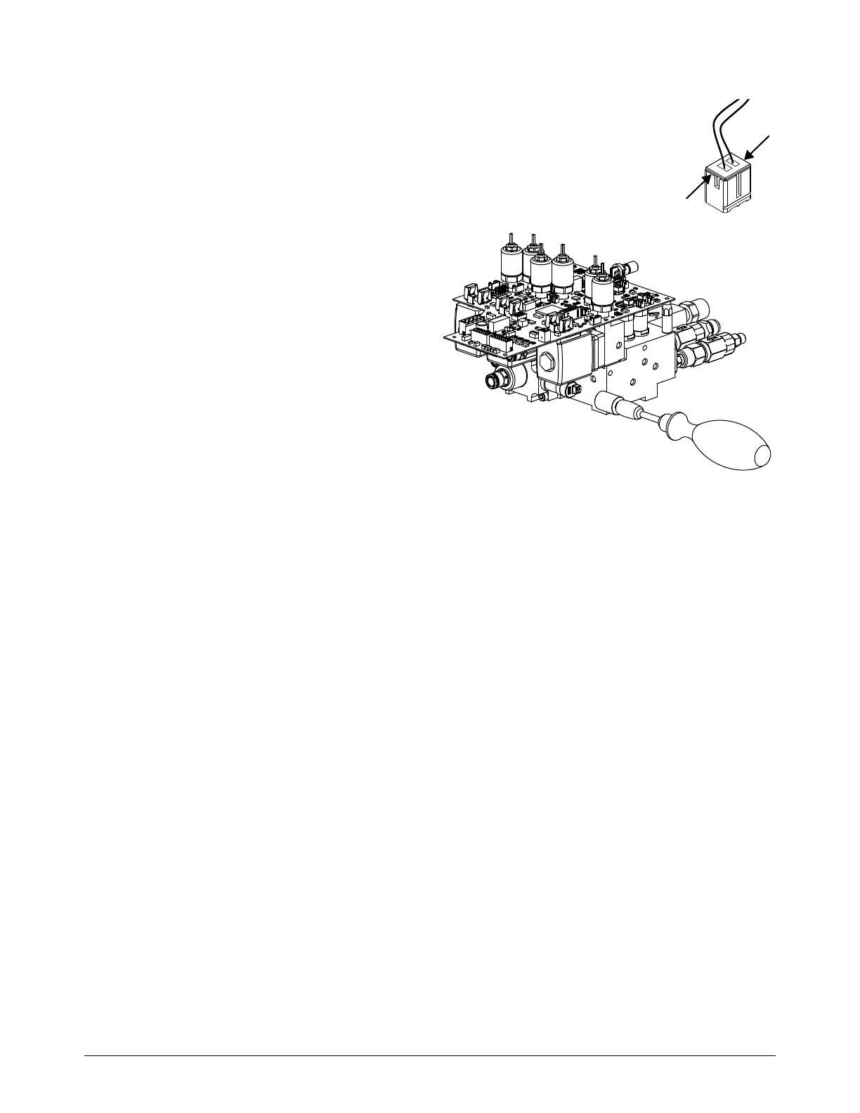
10. Use the edge of the connector to disconnect the wire for V11 from the control
PCB.
Be careful not to pull the wires out of the solenoid valve connector.
11 . Use the tool (229917) to remove the
solenoid valve.
Install the solenoid valve (V11)
1. Use the tool (229917) to install the new solenoid valve. Tighten to 2.5 N∙m (22.1 in∙lb).
2. Connect the wire connector for V11 to the control PCB.
3. Slide the manifold assembly with control PCB through the hole in the panel and into the torch
connect console.
Do not pinch the wires for V11 between the PCB and sheet metal.
4. Use a 3 mm, hexagonal-key wrench to install the 2 screws that hold the manifold assembly.
5. Use a Phillips screwdriver to install the screw on the control PCB.
6. Connect the black, blue, and yellow tubes to the push-to-connect fittings on the manifold
assembly. See How to use push-to-connect fittings on page 90.
7. Install the 2 screws on the ohmic relay side.
8. Install the ohmic relay and bracket. See Install the ohmic relay and bracket on page 94.
9. Install the power connector (J19), ohmic board connector (J27) and V1 connector (J7) on the
control PCB.
10. Connect the gas supply hoses.
11 . Install the side panels.