Gas Connect Consoles
XPR300 Field Service Bulletin 809970 69
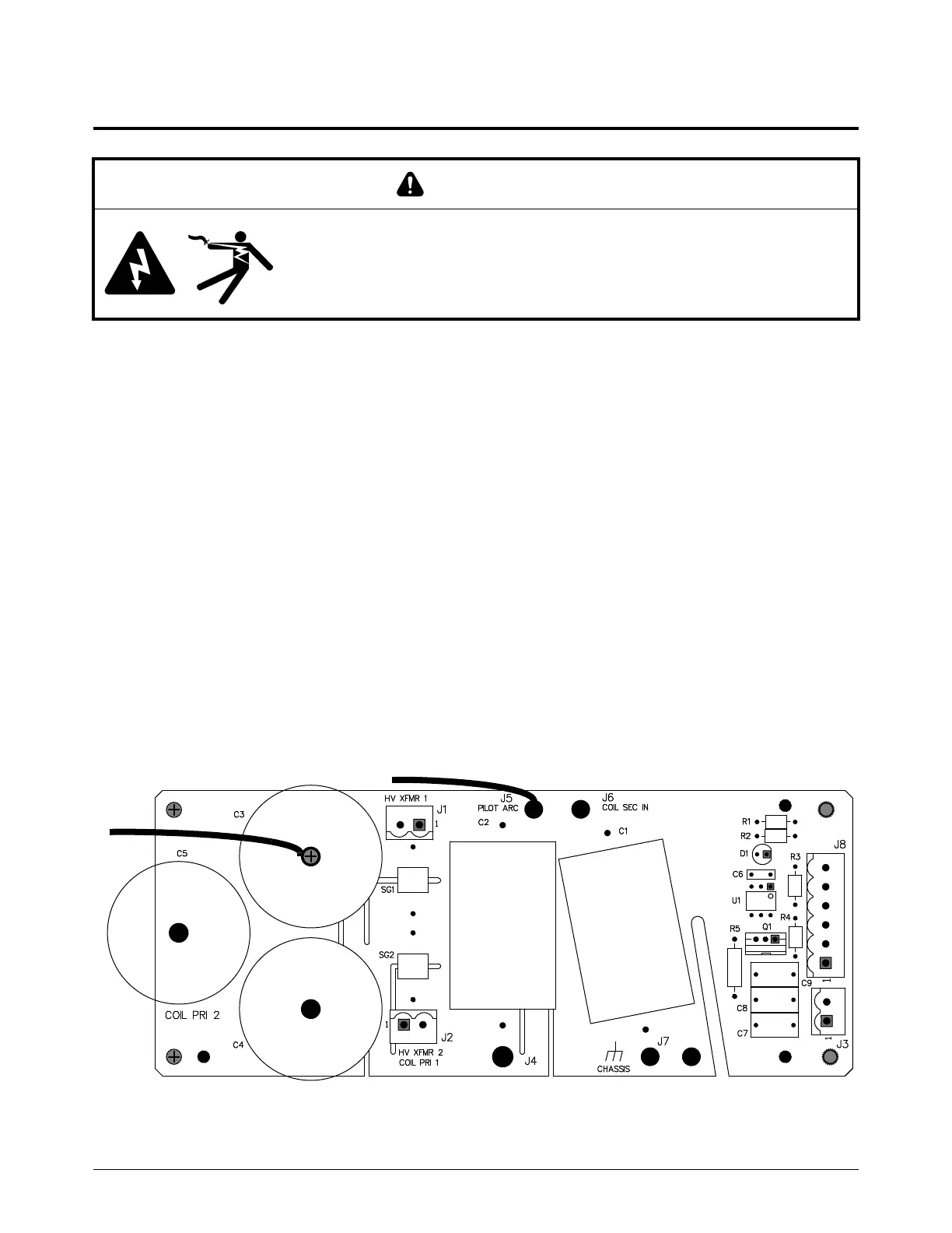
Replace the high-frequency, high-voltage PCB
See Gas connect console high-voltage side parts on page 130 for
location and part number.
1. Complete the following procedures:
a. Remove the power from the cutting system.
b. Remove the top panel.
c. Remove the insulator.
d. Remove the high-voltage-side panel.
See Gas connect console panels on page 87.
Keep all nuts and screws that you remove.
2. Disconnect J1, J2, J3, J5, J7, J8, and the wire to the capacitor.
3. Remove the 2 screws.
4. Remove the 2 thumb screws.
5. Use the screws to install the PCB.
WARNING
ELECTRIC SHOCK
Stored voltages in capacitors can exceed 20,000 V.
All work must be done by a qualified technician.
 Loading...


