Plasma Power Supply
56 809970 Field Service Bulletin XPR300
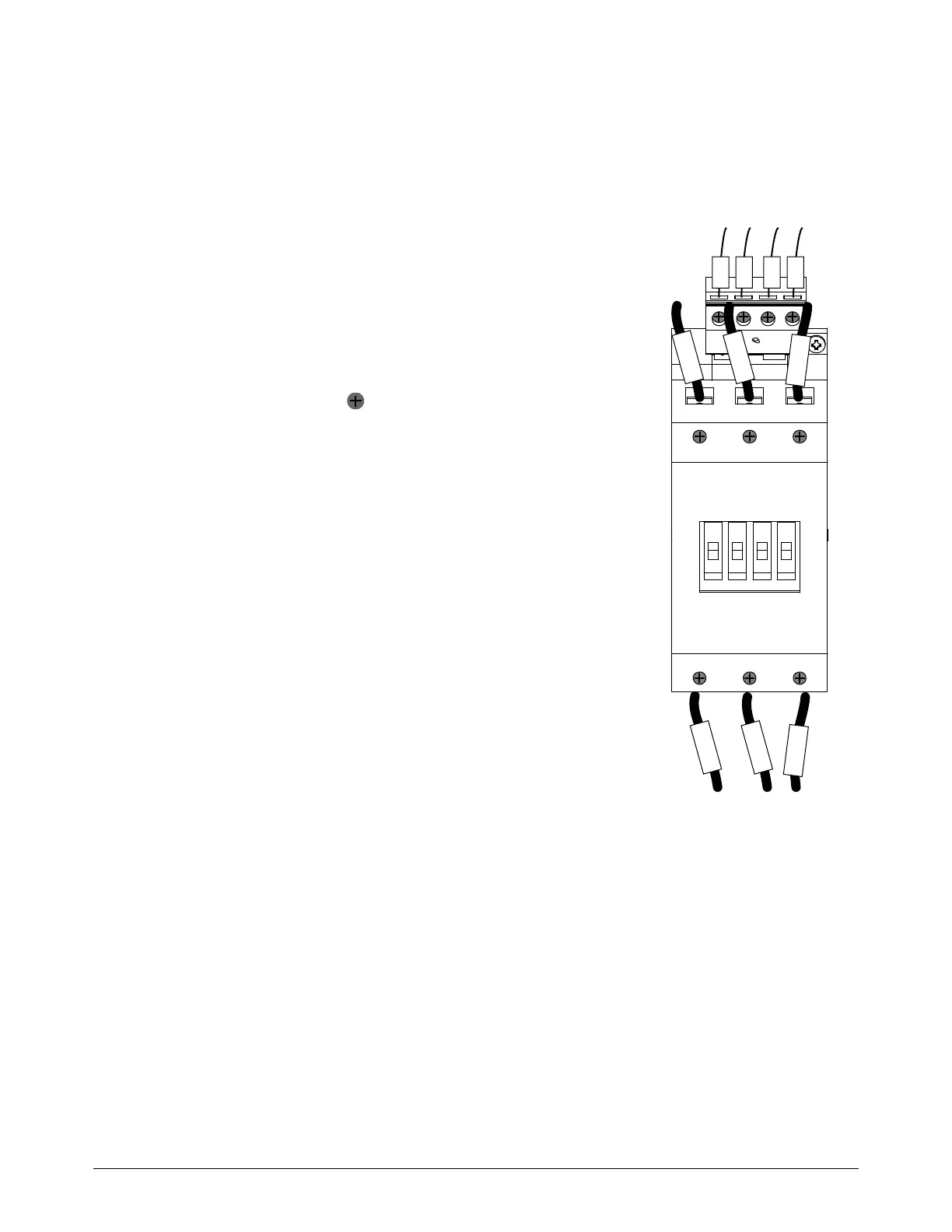
Replace the inrush contactor
See Rear compartment of the plasma power supply on page 128 for
location and part number.
1. Complete the following procedures:
a. Remove the power from the cutting
system.
b. See Remove the rear panel on page 62.
Keep all nuts and screws that you
remove.
2. Loosen the wire screws and remove the
wires.
3. Remove the 2 mounting screws.
4. Use the mounting screws to install the inrush
contactor. Tighten to 2.8 N∙m (25 in∙lb).
5. Install wires L1, B1+, B2-, and N on top of
the inrush contactor. Tighten the screws to
1N∙m (10in∙lb).
6. Install L1, L2, and L3 wires on the top and
bottom of the inrush contactor. Tighten the
screws to 5 N∙m (50 in∙lb).
The wires labeled L1, L2, and L3 on
the top of the inrush contactor must
align with the wires labeled L1, L2,
and L3 on the bottom of the inrush
contactor.
7. Install the rear panel.
L3L2L1
T3T2T1
L2
L1
L3
N
B2-
B1+
L1
L2
L1
L3
To main contactor
To inrush resistor