Plasma Power Supply
XPR300 Field Service Bulletin 809970 35
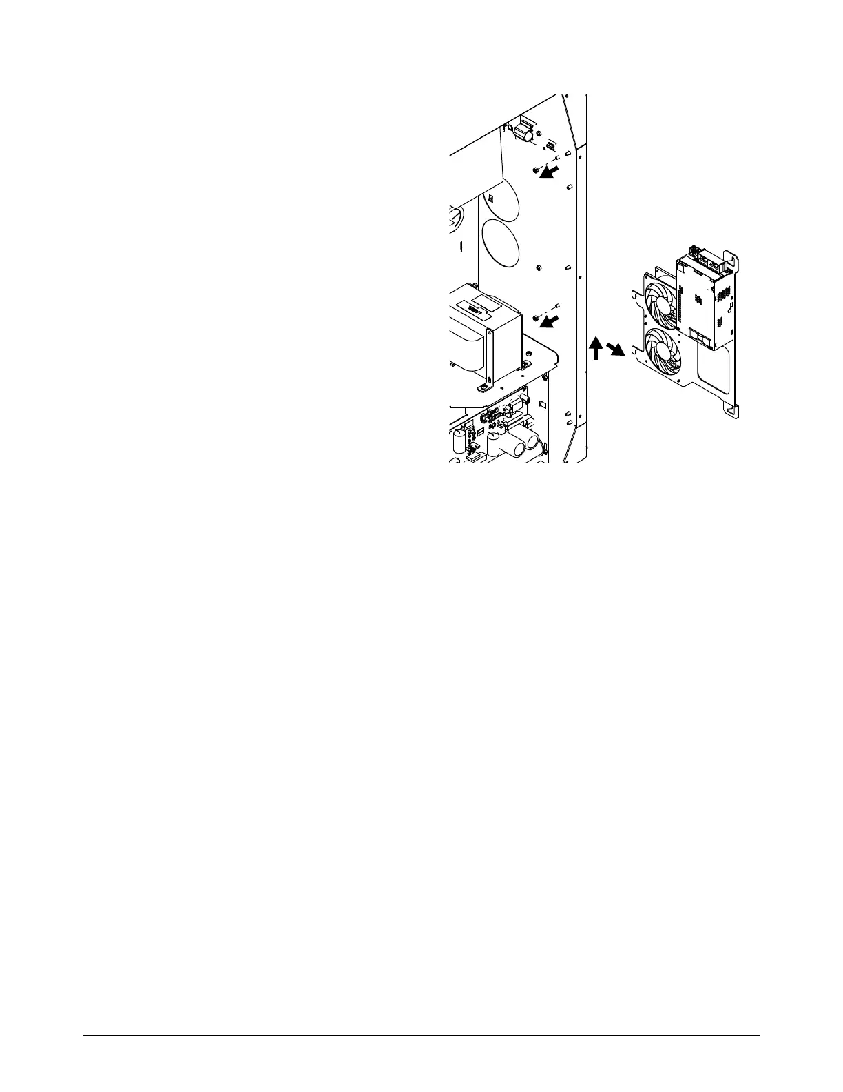
3. On the control side, use a 10 mm,
hexagonal-socket wrench to remove the
2 nuts from the bracket assembly.
4. Remove the bracket assembly from the
plasma power supply.
5. Remove the 2 screws from the control-side
fan that you want to replace.