Notes:
a. To remove printhead cables, hold the cable just above the connector and pull the cable out of the
connector. These are not locking connectors.
b. Some connectors have retaining clips.
c. The sensor connector can be disconnected after the logic board is partially removed.
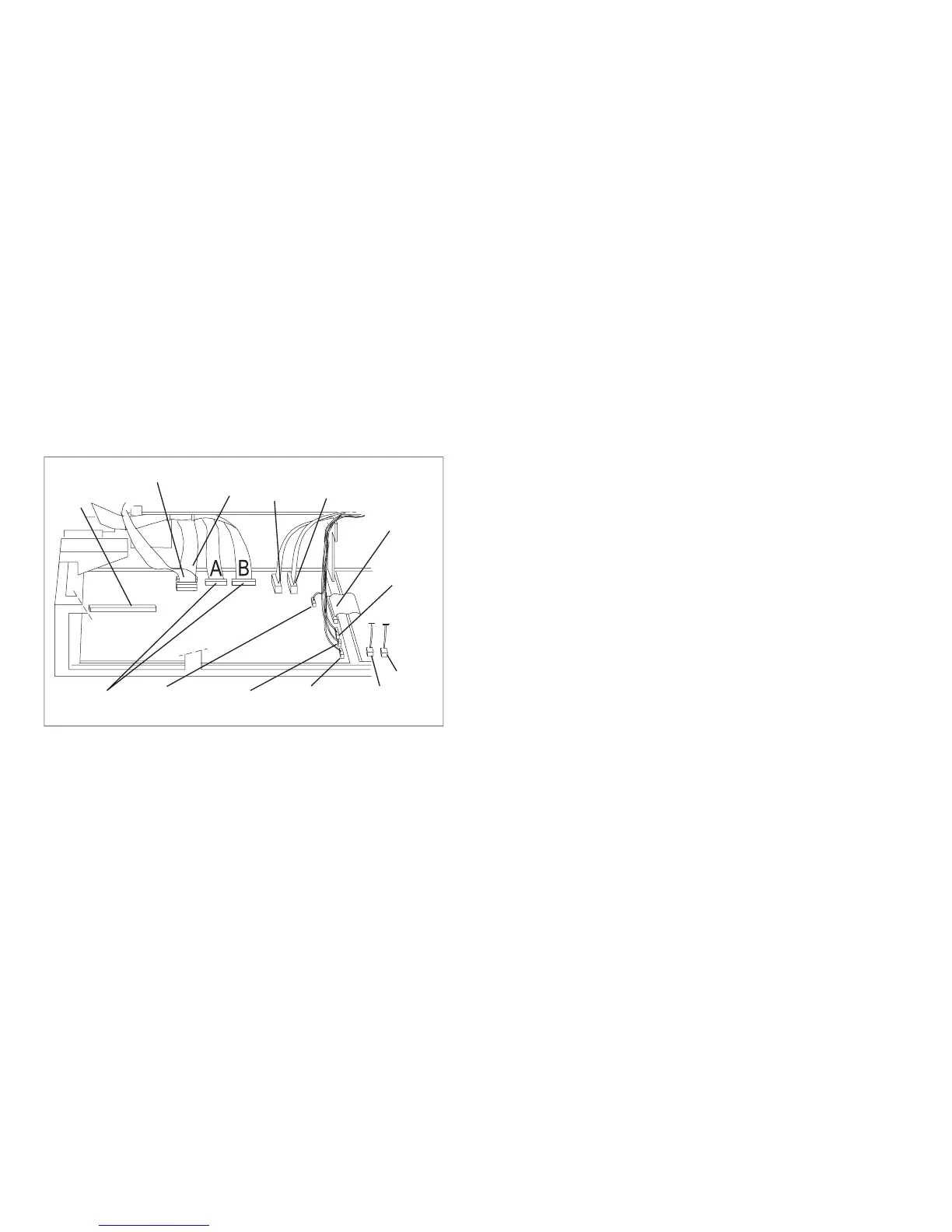
d. Note the connector locations and cable paths to aid installation. Each connector is a unique size.
7. Remove the 6 mounting screws and 2 standoffs. Note the type and location of each screw (see Figure 112).
There are 4 self tapping screws and 2 threaded M3x6 screws.
Operator
Panel
ASF
Stacker
Attachment
Connector
Tractors
Sensors
(Path, Ribbon Motion
and Carriage Home)
Print Head
and Ribbon
Lift Motor
Board
Fan
Power
Supply
Carriage
Motor
AFTA
Ribbon Driver
Motor
Paper
Feed
Motor
Carriage
Fan
E90ALOCA
Figure 111. Connector Locations
Chapter 5. Removals and Adjustments 368