8. Remove the board by pulling the back edge up and out. Note how the front edge is inserted between the
metal tabs on the frame shield.
Replacement
1. Follow the removal steps in reverse order.
Note: Be certain the front edge of the logic board is inserted between the metal tabs on the frame.
2. Run the T&D program in automatic mode. See “How To Run the Test and Diagnostic (T&D) Programs” on
page 201.
Ensure that T&D12, T&D15, T&D16, and T&D17 are adjusted, if indicated.
3. Use the printer configuration printout to verify configuration settings. See
IBM 4247 Printer Model 003 User’s
Guide, S544–5780.
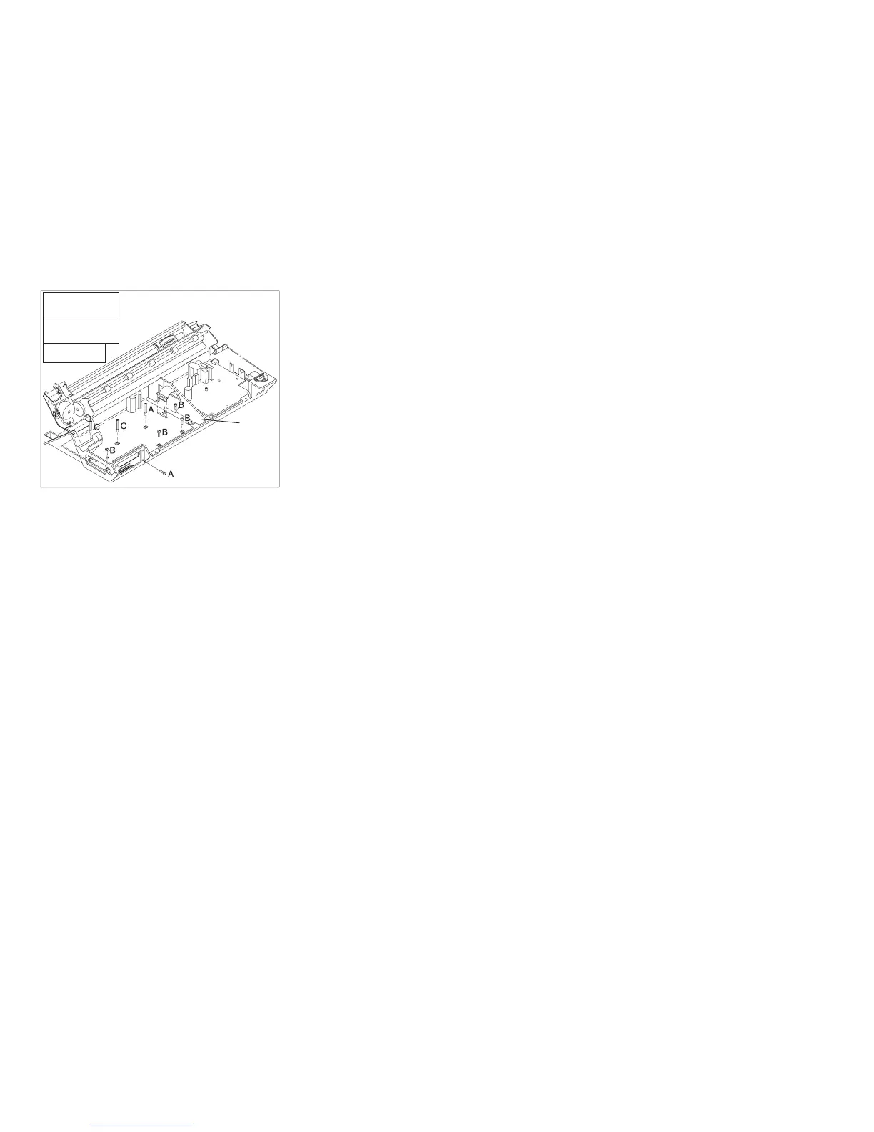
E90ACB5
Threaded
Screw (2)
Self-tapping
Screw (4)
Standoff (2)
A
C
B
Fan
Support
Figure 112. Logic Board Screw Type Locations
Chapter 5. Removals and Adjustments 369