Notes:
a. To remove printhead cables, hold the cable just above the connector and pull the cable out of the
connector. These are not locking connectors.
b. Some connectors have retaining clips.
c. The sensor connector can be disconnected after the logic board is partially removed.
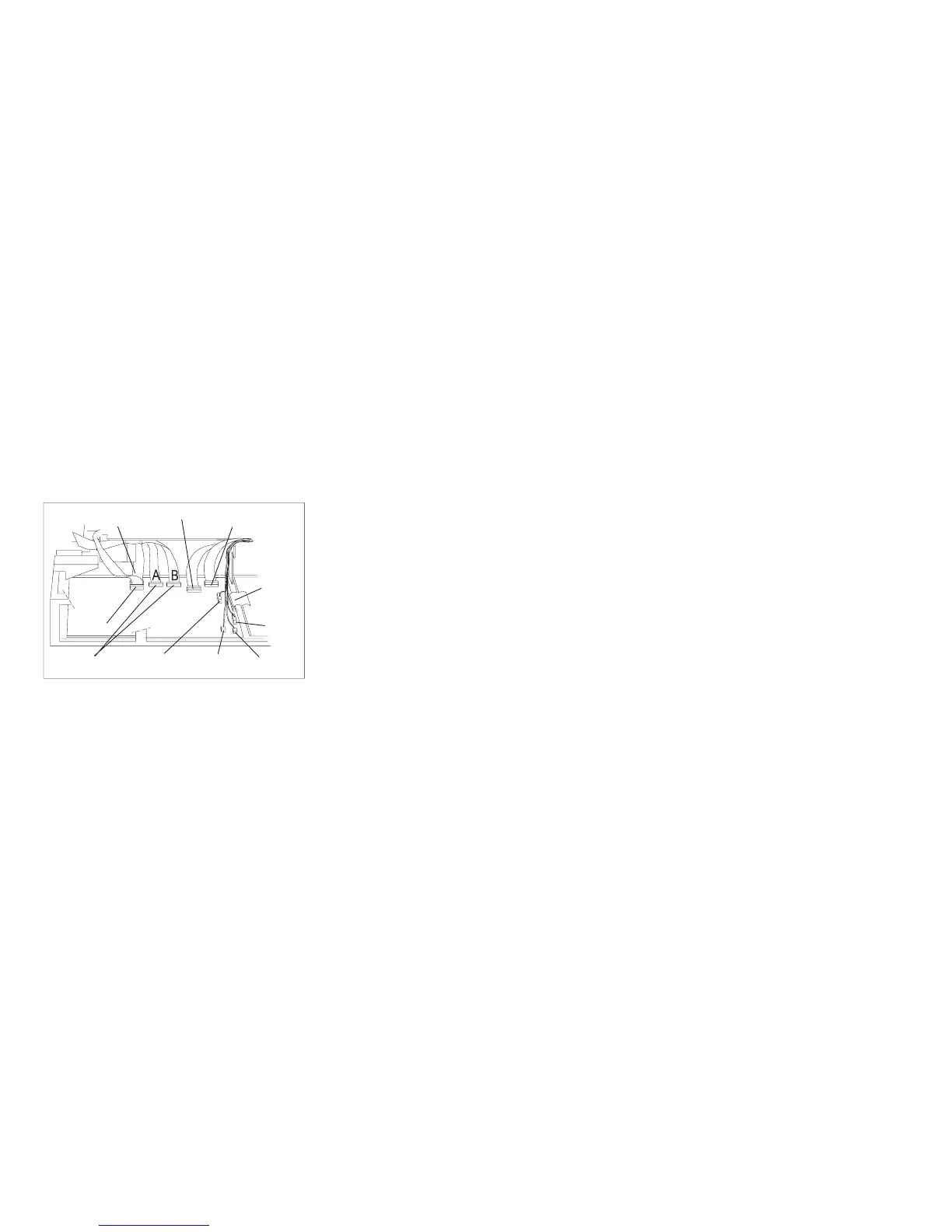
d. Use Figure 114 and Figure 115 on page 373 as reference for the connector locations and cable
paths to aid installation.
e. Each connector is unique in size and shape.
e90alb1
Operator
Panel
Stacker
Print Head and
Ribbon Lift Motor
Tractors
Sensors
Carriage
Motor
AFTA
Ribbon
Motor
Paper
Feed
Motor
Power
Supply
Figure 114. Model A00 Early-Level Logic Board Connector Locations
Chapter 5. Removals and Adjustments 372