7. Remove the mounting screws. Note the type and location of each screw.
8. Lift the rear of the board and pull to remove.
9. Transfer the attachment bezel and screws from the old board to the new board as needed.
e90alb5
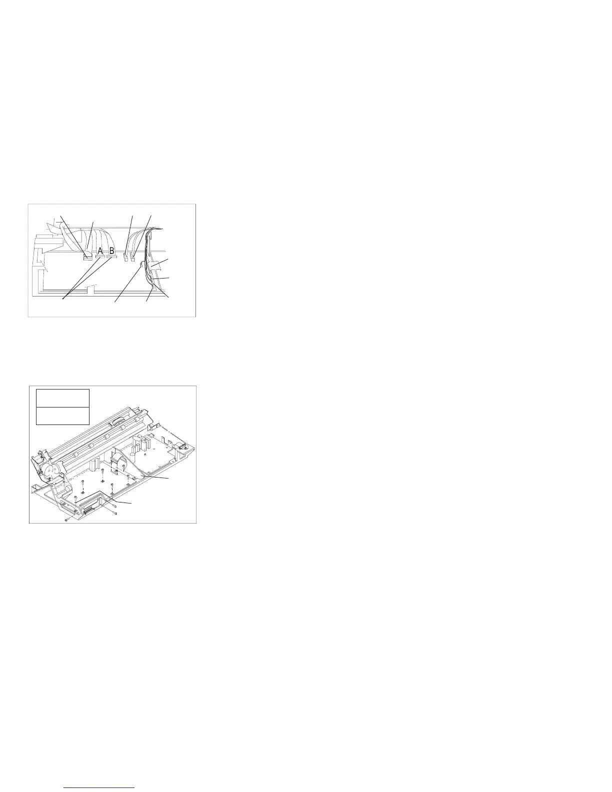
Operator
Panel
Stacker
Print Head and
Ribbon Lift Motor
Tractors
Sensors
Carriage
Motor
AFTA
Ribbon
Motor
Paper
Feed
Motor
Power
Supply
Figure 115. Model A00 Late-Level Logic Board Connector Locations
Threaded
Screw
Self-tapping
Screw
A
B
A
A
A
A
A
B
B
B
B
A
Nonmetal
Washer
Fan
Support
Figure 116. Logic Board Screw Type Locations
Chapter 5. Removals and Adjustments 373