6. Disconnect all connectors from the logic board and remove the jumper for use on the new board. See
Figure 123 on page 384.
Notes:
a. To remove printhead cables, hold the cable just above the connector and pull the cable out of the
connector. These are not locking connectors.
b. Some connectors have retaining clips.
c. The sensor connector can be disconnected after the logic board is partially removed.
d. Note the connector locations and cable paths to aid installation.
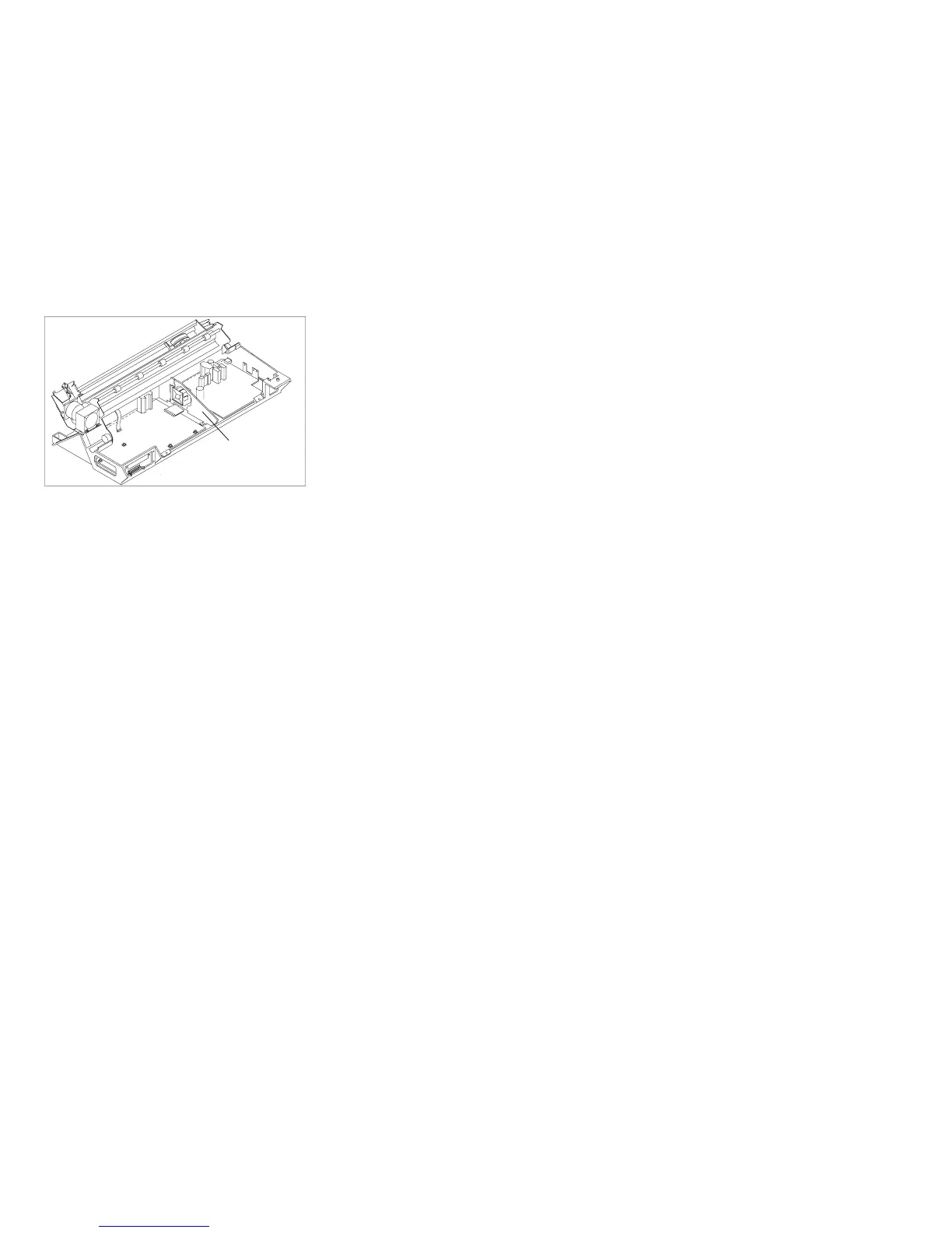
Board Fan
Support
Figure 119. Board Fan Support
Chapter 5. Removals and Adjustments 380