7. Remove the mounting screws and standoffs. Note the type and location of each screw.
8. Lift the rear of the board and pull to remove.
e90alb5
Operator
Panel
Stacker
Print Head and
Ribbon Lift Motor
Tractors
Sensors
Carriage
Motor
AFTA
Ribbon
Motor
Paper
Feed
Motor
Power
Supply
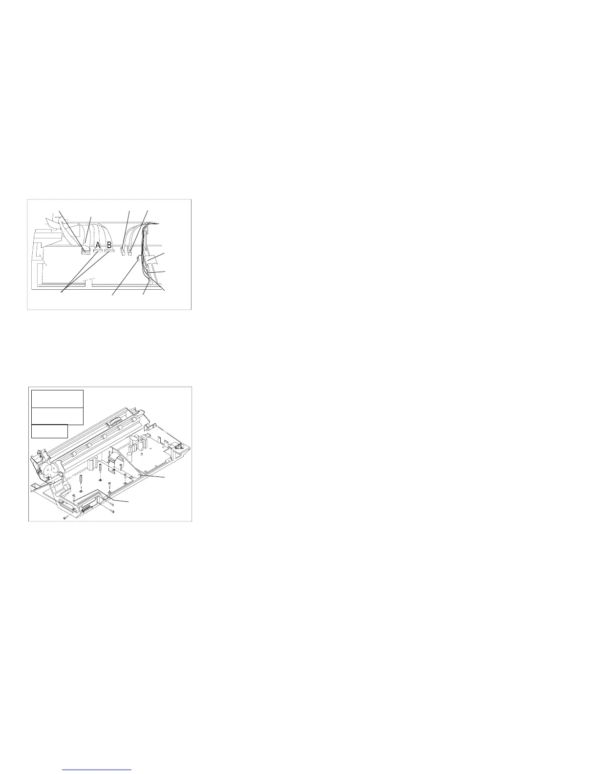
Figure 120. Models 001 and 002 Logic Board Connector Locations.
Model 001 has connectors A and B. Model
002 has only connector B.
Threaded
Screw
Self-tapping
Screw
Standoff
A
C
B
A
A
C
A
C
B
B
B
B
C
Nonmetal
Washer
Fan
Support
Figure 121. Logic Board Screw Type Locations
Chapter 5. Removals and Adjustments 381