EasyManua.ls Logo

IBM 4247

IBM 4247
567 pages
To Next Page IconTo Next Page
To Previous Page IconTo Previous Page
Loading...
Replacement
1. Follow the removal steps in reverse order.
Note: Be certain the front edge of the logic board is inserted between the metal tabs on the frame.
2. Ensure the non-metal washer is installed as shown in Figure 112 on page 369.
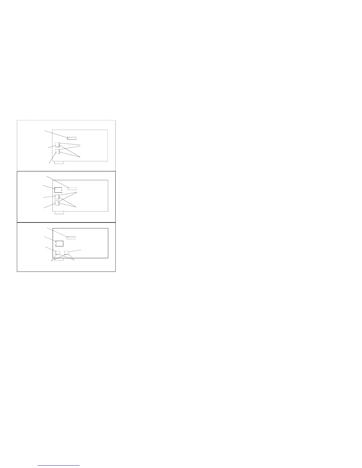
Coax Twinax
Connector
Microcode
Module U54
Microcode
Module U2
Corner
Cut Off
Bevel
4247 001 and 002 Level1
Coax Twinax
Connector
Coax Twinax
Connector
Microcode
Module U57
Microcode
Module U57
Microcode
Module U54
Microcode
Module U2
Microcode
Module U54
Microcode
Module U2
Bevel
Bevel
e90alocd
4247 001 and 002 Level2
4247 001 Level 3
CornerCut Off
CornerCut Off
Figure 122. Models 001 and 002 Rear View of Microcode Module Locations and Orientation
Chapter 5. Removals and Adjustments 383

Table of Contents

Related product manuals