Note: When the non-metal washer is not installed, the frame ground is connected to the dc ground. The
default is washer installed.
3.
The NPS 540+ can be used without an external power supply only if +5 V dc is enabled (supplied) on pin 18
of the printer parallel attachment connector. NPS devices (p/n 30H4082, 30H4083, 30H4055) cannot be
powered by pin 18 and always require an external +12 V ac power supply. There is no danger of damaging
any NPS or other computer devices when +5 V dc is enabled on pin 18.
The new logic board you will receive will have a 2 pin jumper installed on either a 2 pin or a 3 pin connector
located near the parallel attachment connector.
To attach the NPS Ethernet 540+ (p/n 30H4054) to the 4247 printer without an external power supply:
a. Find the 2 pin jumper and connector.
b. If a 2 pin jumper is installed on a 2 pin connector then+5Vdcisenabled to pin 18.
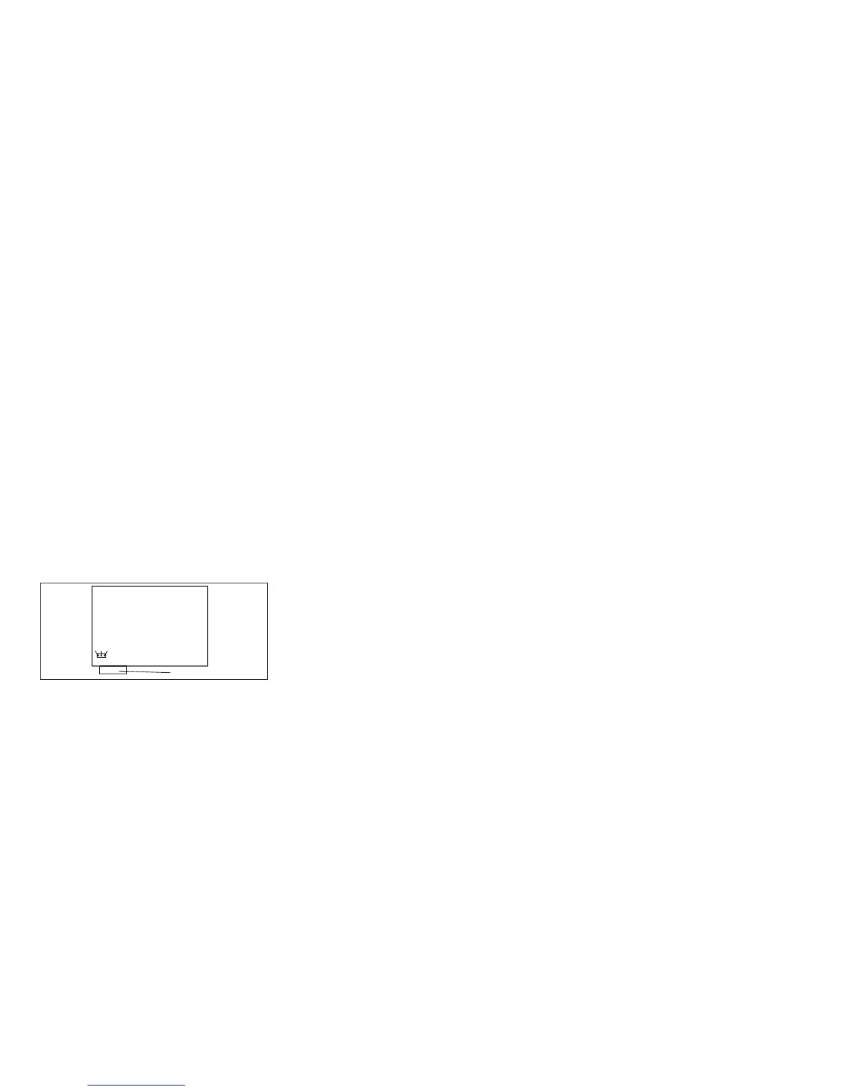
c. If a 2 pin jumper is installed on a 3 pin connector, as shown in Figure 4-18, use the chart below and verify
the jumper is installed to enable +5 V dc on pin 18. If the jumper is not installed correctly, move it to the
pins shown in the chart.
Note: If after installing the logic board, the NPS 540+ power light is not lighted, check for+5Vdconpin18
with a volt meter (pin 18 is shown on connector).
123
Logic Board
Parallel Connector
Figure 123. Model 001/002 Logic Board Jumper Location.
(Viewed From Rear)
Chapter 5. Removals and Adjustments 384