5. Perform the following:
a. Remove the 2 ground strip screws.
b. Remove the 2 mounting screws.
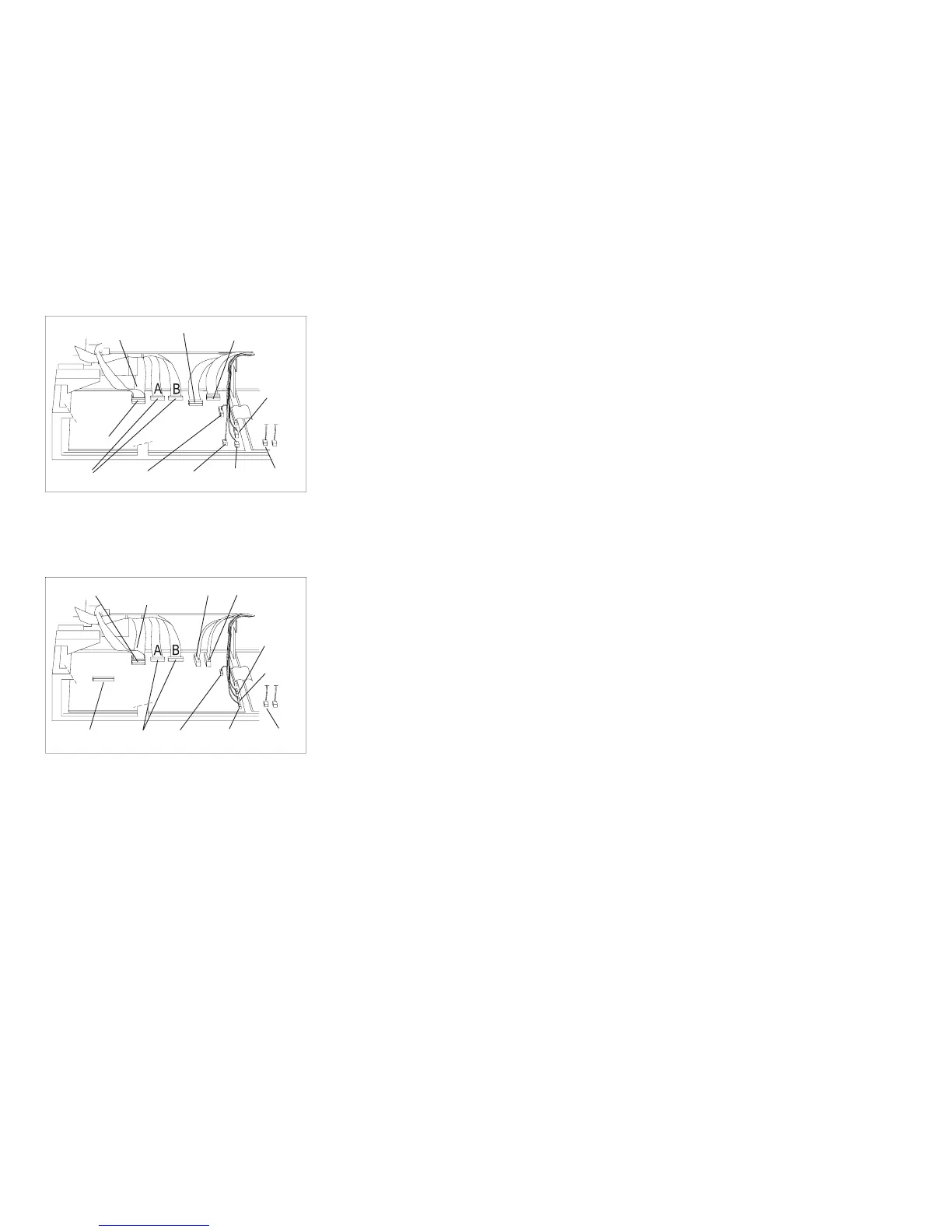
Operator
Panel
Stacker
Print
Head
Tractors
Sensors
Carriage
Motor
AFTA
Ribbon
Motor
Paper
Feed
Motor
Carriage
Fan
Figure 179. Logic Board Connector Locations - Model A00 Early-Level
Operator
Panel
Stacker
Print
Head
Coax/Twinax
Card
Tractors
Sensors
Carriage
Motor
AFTA
Ribbon
Motor
Paper
Feed
Motor
Carriage
Fan
Figure 180. Logic Board Connector Locations - Model A00 Late-Level and Models 001, 002.
Models 001 and 003
have connectors A and B. Model 002 has only connector B.
Chapter 5. Removals and Adjustments 445