Figure 4 on page 53 shows the location and orientation of the attachment card microcode module (S1) on the
Level 1 (long) attachment card.
Figure 5 on page 53 shows the location and orientation of the attachment card microcode module on the Level 2
(short) attachment card. The position of the corner cut and the beveled edge help you determine the orientation of
the microcode module.
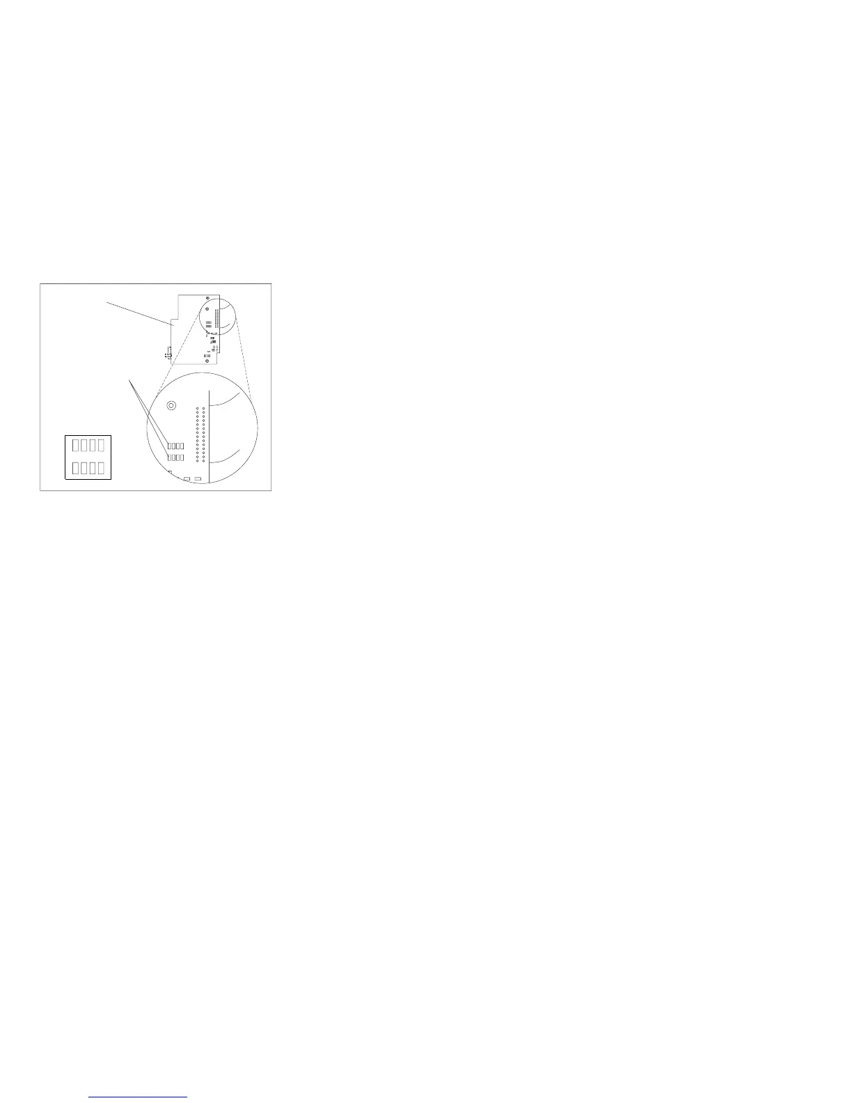
Bottom View
of the
Attachment Card
Showing the
Feature Resistors
Feature Resistors
Feature Resistors
as Shown in Table
e90act05
Figure 3. Models 001 and 002, attachment card Feature Resistors [Level 2 (Short) Card]
Chapter 1. Diagnosing Problems 52