Use Figure 2 on page 51, Figure 4, and Figure 7 on page 55 to verify that the:
v Attachment card feature resistors and S1 module label match your host connection feature.
v S1 module is installed in the correct orientation. The dotted line depicted on the S1 module in Figure 3 on
page 52 represents the orientation of the beveled edge.
On the Level 2 (short) attachment card, use the orientation marks to help you position the microcode module in
the module socket.
Corner
Cut Off
Bevel
S1
e90act08
248 mm
9.7 in.
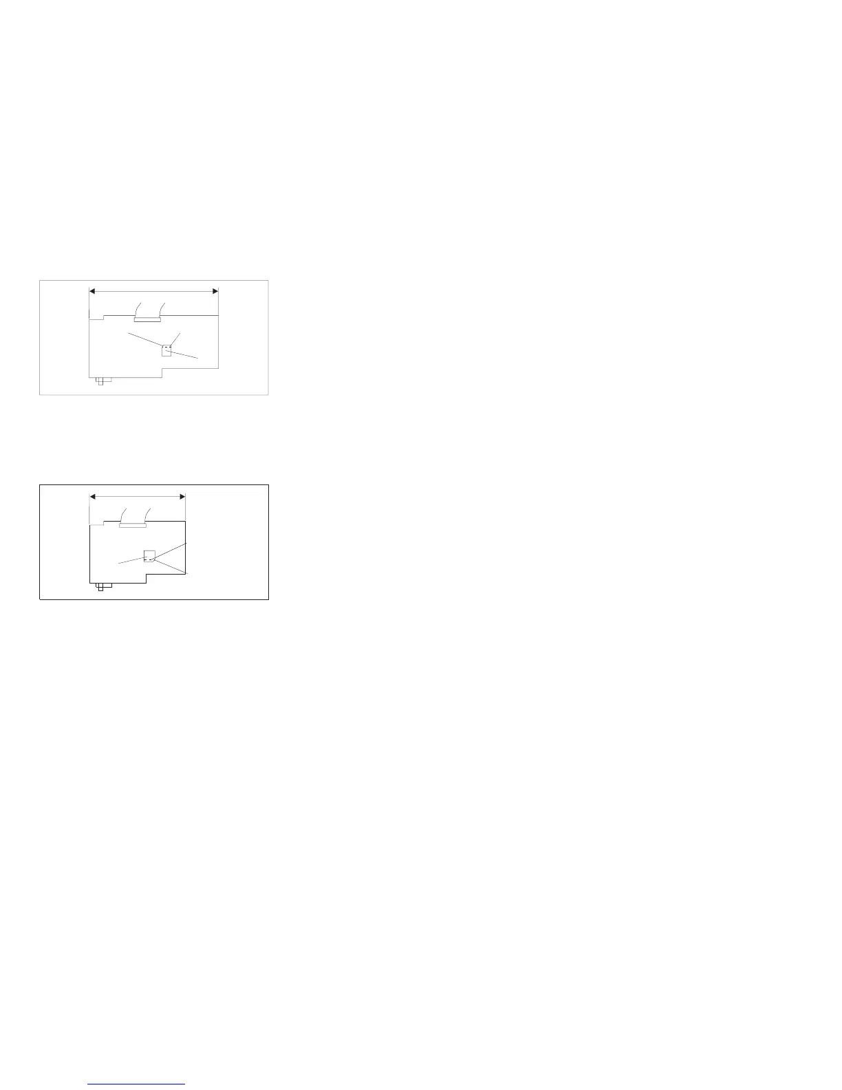
Figure 4. Models 001 and 002, Placement of S1 Microcode Module - Long Card.
The length of this attachment
card is approximately 248 mm (9.7 in.).
Corner
Cut Off
Bevel
S1
e90act10
182 mm
7.2 in.
Figure 5. Models 001 and 002, Placement of S1 Microcode Module - Short Card.
The length of this attachment
card is approximately 182 mm (7.2 in.).
Chapter 1. Diagnosing Problems 53