7: BASIC INSTRUCTIONS
OPENNET CONTROLLER USER’S MANUAL 7-21
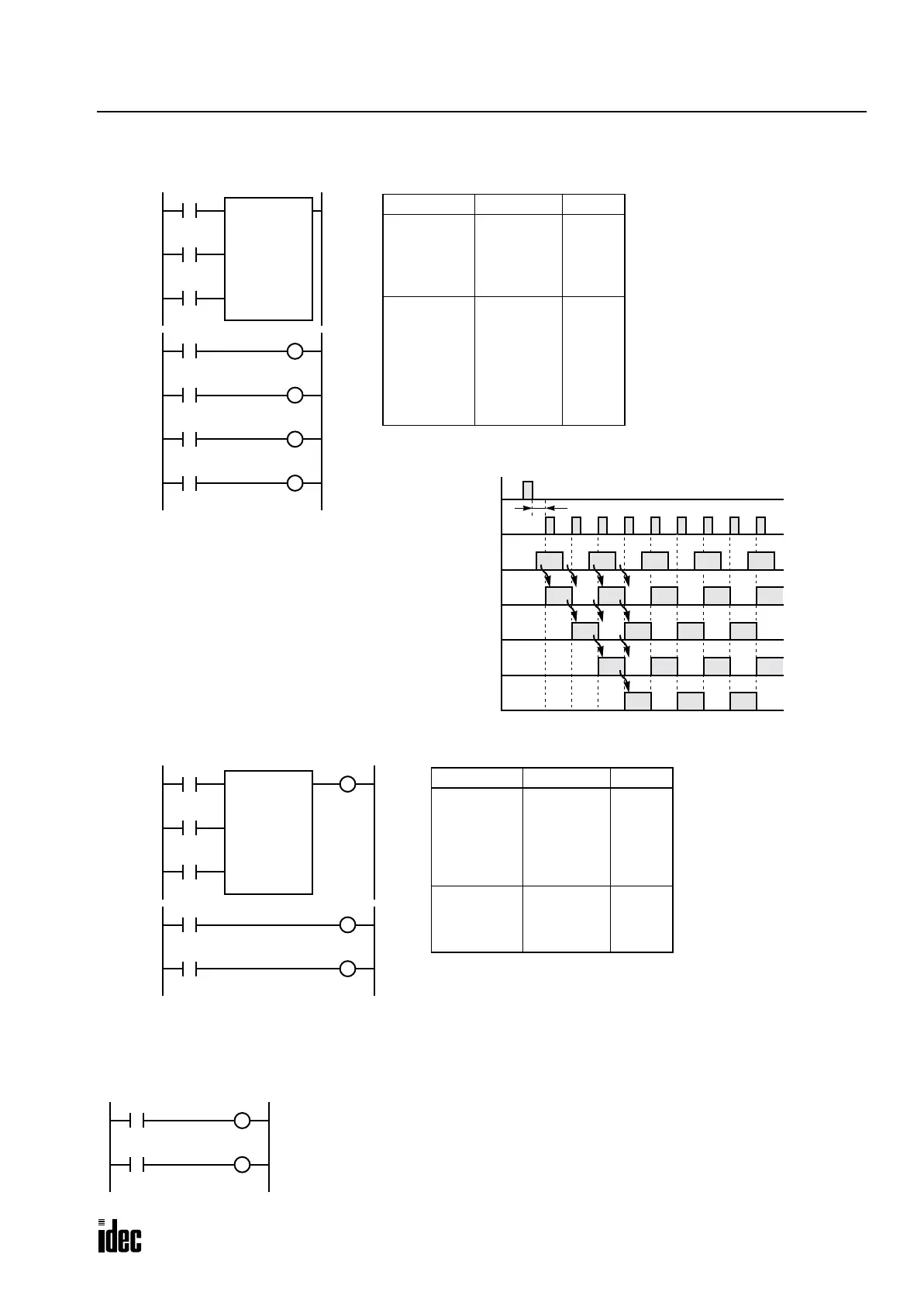
Forward Shift Register (SFR), continued
Setting and Resetting Shift Register Bits
Reset Input I0
ON
OFF
Pulse Input I1
ON
OFF
Data Input I2
ON
OFF
Timing Chart
R1/Q1
ON
OFF
One scan or more is required
R0/Q0
ON
OFF
R3/Q3
ON
OFF
R2/Q2
ON
OFF
Ladder Diagram
I0
I1
SFR R0
4
I2
Reset
Pulse
Data
R0
Rung 2
Rung 1
R1
R2
R3
Prgm Adrs Instruction Data
Rung 1 0
1
2
3
4
LOD
LOD
LOD
SFR
I0
I1
I2
R0
4
Rung 2 5
6
7
8
9
10
11
12
LOD
OUT
LOD
OUT
LOD
OUT
LOD
OUT
R0
Q0
R1
Q1
R2
Q2
R3
Q3
Program List
Q3
Q0
Q1
Q2
• The last bit status output can be programmed directly after
the SFR instruction. In this example, the status of bit R3 is
read to output Q3.
• Each bit can be loaded using the LOD R# instruction.
Prgm Adrs Instruction Data
Rung 1 0
1
2
3
4
5
LOD
LOD
LOD
SFR
OUT
I1
I2
I3
R0
4
Q3
Rung 2 6
7
8
9
LOD
OUT
LOD
OUT
R0
Q0
R1
Q1
Program ListLadder Diagram
I1
I2
SFR R0
4
I3
Reset
Pulse
Data
R0
Rung 2
Rung 1
R1
Q3
Q0
Q1
I1
I0
• Any shift register bit can be turned on using the SET instruction.
• Any shift register bit can be turned off using the RST instruction.
• The SET or RST instruction is actuated by any input condition.
R0
S
R3
R
Phone: 800.894.0412 - Fax: 888.723.4773 - Web: www.clrwtr.com - Email: info@clrwtr.com

 Loading...

