20: PID INSTRUCTION
OPENNET CONTROLLER USER’S MANUAL 20-15
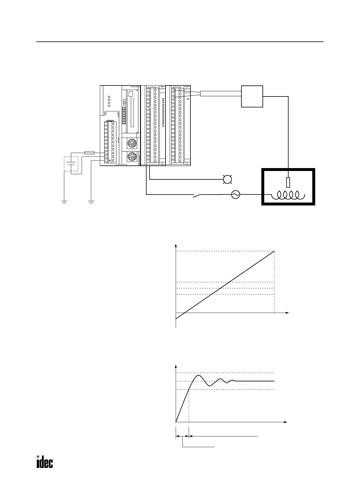
System Setup
Digital Output from Analog Input Module vs. Process Variable after Conversion
Temperature Control by Auto Tuning and PID Action
ABG
RS485
COM A B Z
HSC
OUT
+24V 0V
POWER
RUN
ERROR
HSC OUT
1
2
3
4
5
6
7
8
9
10
11
12
13
14
15
16
17
18
19
20
A/D
+
_
24V DC
Fuse
CPU Module
Relay Output Module
FC3A-R161
Analog Input Module
FC3A-AD1261
0
1
2
3
4
5
6
7
10
11
12
13
14
15
16
17
1
2
3
4
5
6
7
8
9
10
11
12
13
14
15
16
17
18
19
20
Ry
OUT
Transducer
–50° to 500°C
Thermocouple
High Alarm LightOutput Q1
Output Q0 Heater Power Switch
L
Heater
High Alarm Value (S1+14): 2500 (250°C)
4000
Linear Conversion Minimum Value (S1+6): –500 (–50°C)
0
Linear Conversion Maximum Value (S1+5): 5000 (500°C)
Set Point (S3): 2000 (200°C)
AT Set Point (S1+21): 1500 (150°C)
Digital Output from Analog Input Module
Process Variable after Conversion (S1+0)
Process Variable after Conversion (S1+0)
Time
High Alarm Value (S1+14): 2500 (250°C)
Set Point (S3): 2000 (200°C)
AT Set Point (S1+21): 1500 (150°C)
Auto Tuning
PID Action
Phone: 800.894.0412 - Fax: 888.723.4773 - Web: www.clrwtr.com - Email: info@clrwtr.com

 Loading...

