20: PID INSTRUCTION
20-16 OPENNET CONTROLLER USER’S MANUAL
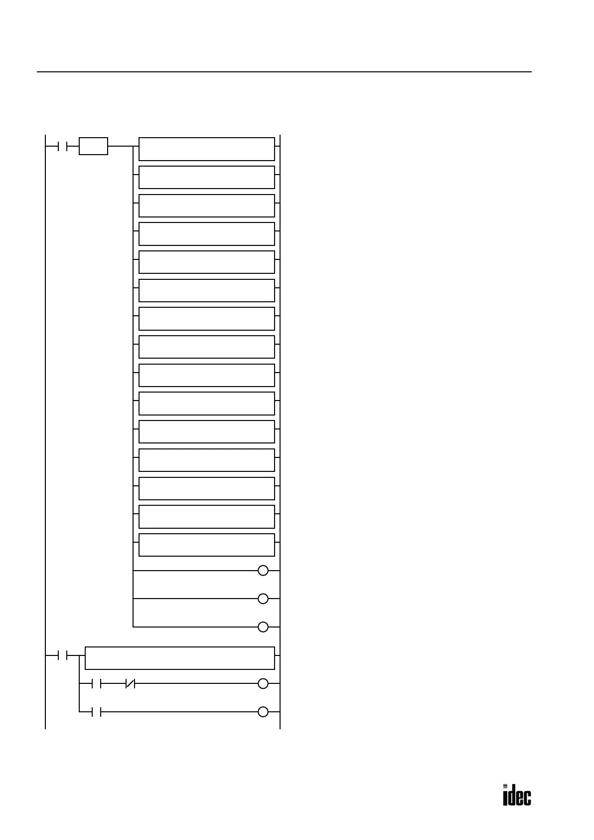
Ladder Program
The ladder diagram shown below describes an example of using the PID instruction. The user program must be modified
according to the application and simulation must be performed before actual operation.
When input I0 is turned on, 0 is stored to 27 data registers
D0 through D26 designated as control registers.
D3 (operation mode): 1 (AT+PID)
D4 (linear conversion): 1 (enable linear conversion)
D5 (linear conversion maximum value): 5000 (500°C)
D6 (linear conversion minimum value): –500 (–50°C)
D10 (integral start coefficient): 0 (100%)
D11 (input filter coefficient): 70 (70%)
D12 (sampling period): 50 (500 msec)
D13 (control period): 10 (1 sec)
D14 (high alarm value): 2500 (250°C)
D19 (AT sampling period): 150 (1.5 sec)
D20 (AT control period): 30 (3 sec)
D21 (AT set point): 1500 (150°C)
D22 (AT output manipulated variable): 100 (100%)
D100 (set point): 2000 (200°C)
S1 –
1
D1 –
D3
MOV(W)
REP
S1 –
1
D1 –
D4
MOV(W) REP
S1 –
5000
D1 –
D5
MOV(I) REP
S1 –
–500
D1 –
D6
MOV(I) REP
S1 –
70
D1 –
D11
MOV(W)
REP
S1 –
50
D1 –
D12
MOV(W) REP
S1 –
10
D1 –
D13
MOV(W) REP
S1 –
2500
D1 –
D14
MOV(W) REP
S1 –
150
D1 –
D19
MOV(W) REP
S1 –
30
D1 –
D20
MOV(W)
REP
S1 –
1500
D1 –
D21
MOV(W) REP
S1 –
100
D1 –
D22
MOV(W) REP
S1 –
2000
D1 –
D100
MOV(W) REP
M3
R
M2
R
M1
R
When input I0 is turned on, 3 internal relays M1 through
M3 designated as control relays are turned off.
M1 (auto/manual mode): Auto mode
M2 (output manipulated variable limit enable): Disable
M3 (integral start coefficient disable): Enable
While input I0 is on, the PID instruction is executed.
D0-D26: control registers
M0-M7: control relays
D100: set point
L100: process variable
D102: manipulated variable
When internal relay M6 (control output) is turned on, out-
put Q0 (heater power switch) is turned on.
When internal relay M4 (high alarm output) is turned on,
output Q1 (high alarm light) is turned on.
S1 –
0
D1 R
D0
MOV(W) REP
27
S1 –
0
D1 –
D10
MOV(W) REP
I0
SOTU
I0
D1
D102
S1
D0
S2
M0
S3
D100
PID
S4
L100
M6
M4
Q0
Q1
M4
Continued on the next page.
Phone: 800.894.0412 - Fax: 888.723.4773 - Web: www.clrwtr.com - Email: info@clrwtr.com

 Loading...

